Power Up: DLP-528 363-205-401
Page 2 of 4 Issue 7, March 1997
PRELIMINARY DRAFT
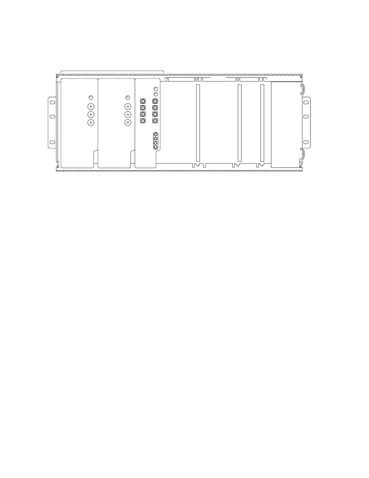
Figure 1 – Ringing Generator Installed in Ring Shelf
6. Condition DMM to measure DC volts.
7. On
RING GEN1
, connect DMM test leads to −
48V
jack and
GND
jack [Figure
1].
8. Does DMM indicate between −43 and −56 volts?
If
YES,
then proceed to Step
14.
If
NO,
then continue with Step
9.
9. Replace
RINGING GENERATOR
. Does DMM indicate between −43 and −56
volts?
If
YES,
then proceed to Step
14.
If
NO,
then continue with Step
10.
10. On right-hand side of ring shelf, disconnect
P117
connector. Connect DMM
test leads to pin 8 (−48V) and pin 9 (−48V RTN) [Figure 2].
GND
-20HZ
FAIL
-48V
GENERATOR
RINGING
3C
GND
-20HZ
GENERATOR
RINGING
3C
FAIL
-48V
GROUP 1
RING GEN 2
+20HZA
+20HZB
-48V
GND
RING GEN 1 RCU
RCU
RMN
1
+20HZ
0.5A
-20HZ
0.5A
2
3
4
AUG3
RMJ
GROUP 2
RING GEN 1 RING GEN 2 RCU
Lucent Lucent Lucent
 Loading...