363-205-401 Power Up: DLP-528
Issue 7, March 1997 Page 3 of 4
PRELIMINARY DRAFT
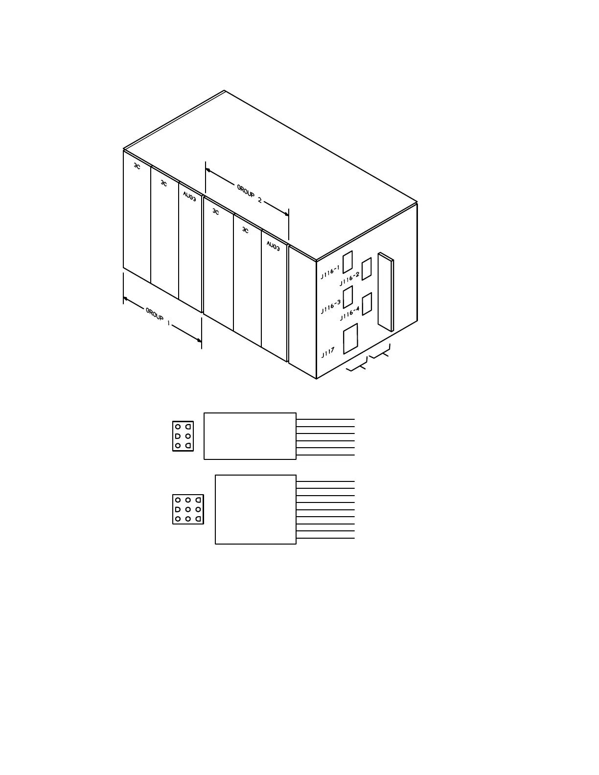
Figure 2 – Connections to Ring Shelf
11. Does DMM indicate between −43 and −56 volts?
If
YES,
then proceed to Step
13.
If
NO,
then continue with Step
12.
12. Refer to SD-7C158-01 to check connectors on 80E bulk power cabinet and
correct wiring problem. Repeat from Step
7.
4
5
6
1
2
3
1
2
3
7
8
9
4
5
6
(-20 HZ)
OUTPUT
(-48V)
J117
2
INPUT
J116-1 THRU J116-4
OR
(W-BL) -20 HZ-A
(BL) 20 HZ RTN-A
(W-G) +20 HZ-A
(W-O) -20 HZ-B
(0) 20 HZ RTN-B
(G) +20 HZ-B
P116-2
P116-1
(VIO) MN2
3
4
5
6
P117
(WHT) -48 RTN
(BLK) -48V
NC
(RED) FRQ
NC
(ORN) MJ2
(YEL) MN1
(BLU) MJ1
9
8
7
6
5
4
3
2
1
1
 Loading...