EasyManuals Logo

Lumel RE72 Quick Start

Lumel RE72
To Next Page IconTo Next Page
To Previous Page IconTo Previous Page
Page #28 background imageLoading...
Page #28 background image
pl EN

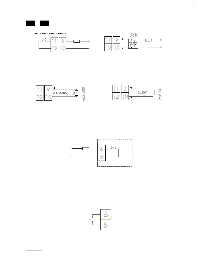
Fig. 7. Control outputs/ alarming
Output 1, 2 – relay
Output 1, 2 – voltage 0/5 V
Output 1, 2 – continuous
current 0/4...20 mA
Output 1, 2 – continuous voltage
0...5/10 V
Output 3 – relay








Load
OUT1OUT2
supply
9
11
10
12
Load
+
-
SSR
OUT1OUT2
supply
9
11
10
12
+
-
 load
 load
supply
supply
Load
Supply
6
5
OUT3
supply
 load
0/4...20mA
Laod
max. 500
+
-
OUT1OUT2
911
1012
V
0...10
Load
min.1k
+
-
911
1012
OUT1OUT2
 load
 load
6
5

Fig. 8. Binary input

Other manuals for Lumel RE72

Questions and Answers:

Question and Answer IconNeed help?

Do you have a question about the Lumel RE72 and is the answer not in the manual?

Lumel RE72 Specifications

General IconGeneral
BrandLumel
ModelRE72
CategoryController
LanguageEnglish