Do you have a question about the Lumen Dynamics Group OmniCure LX400+ and is the answer not in the manual?
Lists system-level error codes and their potential causes.
Lists LED head specific error codes and their meanings.
Details the technical specifications of the main controller unit.
Specifies operating, transport, and storage environmental requirements.
Explains symbols used in the manual for safety and operational context.
Details critical warnings and cautions for safe operation and handling.
Highlights specific caution labels related to UV radiation and hot surfaces.
Details protective eyewear requirements and user responsibility for UV exposure.
Warns about potential hazardous optical radiation and adherence to installation guidelines.
Advises against staring at the LED aperture and using protective clothing/shielding.
Emphasizes secure mounting of LED heads and the use of the key switch.
Warns about hazardous voltages and recommends qualified personnel for repairs.
Advises against leaving unattended units and connecting unauthorized equipment.
Warns that using unspecified controls may lead to hazardous radiation exposure.
Provides guidance on cleaning controller and LED head assemblies safely.
Details hazardous distance limits for different LED head models and hazard types.
Provides optical safety data for the 385nm LED head model.
Details optical safety specifications for the 400nm LED head model.
Presents test results for radiance summations across different head models.
Shows test results for irradiance summations, indicating compliance with risk groups.
Summarizes risk group test results for radiance summations across head models.
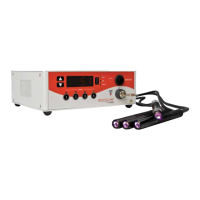
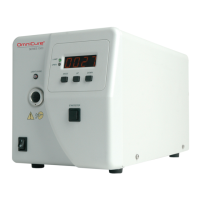
Lists and describes the physical parts included in the system package.
Identifies and explains the functions of the controller's front panel interface.
Details the connections and ports available on the rear of the controller.
Outlines the primary steps for setting up the system and its components.
Describes the process for safely attaching and detaching the protective cap of the LED head.
Explains how to install and remove the mounting clamp for the LED head.
Provides instructions for replacing the optical lenses on the LED head assembly.
Illustrates the lens and housing assembly and how to place the protective cap.
Shows the optimal position for the clamp on the LED head for performance.
Illustrates common ways the system can be installed.
Demonstrates how to use an extension rod for mounting.
Details the sequence for turning the system on and off safely.
Details automatic mode settings and powering down the unit.
Explains how to navigate and select different operating modes of the controller.
Describes how to set and adjust the UV light emission time.
Explains how to adjust the intensity of the UV light output.
Clarifies the meaning of the 'OFF' display status for channels.
Explains the 'OFF' display behavior during process countdowns.
Details how to select between manual and automatic trigger modes.
Guides on operating the LED emission manually for specific durations.
Explains how to set up automatic timed UV light emission sequences.
Details setting intensity and time for automatic LED emission.
Shows how to view the accumulated operating hours for each LED head.
Describes how to switch the display between timer and temperature modes.
Explains how to view the operating temperature of the LED heads.
Summarizes the functions of the front panel buttons and their conditions.
Explains the status and meaning of the controller's LED indicators.
Provides a reference for different display formats and their definitions.
Lists possible alarm conditions and how to interpret them.
Details the connection and operation of the foot pedal for system control.
Details the configurations for assigning foot pedals to specific channels.
Describes the PLC connector and its pin-out for external integration.
Explains the functionality of individual signals on the PLC connector.
Continues explaining PLC signal descriptions for various pins.
Continues explaining PLC signal descriptions for various pins.
Continues explaining PLC signal descriptions for various pins.
Specifies characteristics and logic levels for output signals.
Specifies the requirements for digital and analog input signals.
Illustrates typical output signal circuitry for active low and active high configurations.
Details the connection and function of the remote safety interlock.
Provides essential cautions and warnings for routine maintenance procedures.
Provides detailed steps for cleaning the LED head and lens assembly.
Outlines the specific steps and materials for cleaning the lens.
Gives instructions for cleaning the external surfaces of the controller unit.
Explains how system and head errors are indicated and handled.
Lists system-level error codes and their potential causes.
Lists LED head specific error codes and their meanings.
Provides common symptoms and their likely causes for troubleshooting.
Continues listing causes and checks for specific error codes.
Details the technical specifications of the main controller unit.
Refers to a separate guide for specific LED head technical details.
Specifies operating, transport, and storage environmental requirements.
Lists relevant product safety, EMC, and CE compliance standards.
Provides substance information as required by China RoHS regulations.
Explains disposal and environmental regulations related to WEEE directive.
Provides information regarding FCC compliance for Class A digital devices.
Lists product components and their corresponding part numbers.
| Input Voltage | 100-240 VAC |
|---|---|
| Frequency | 50/60 Hz |
| Wavelength | 320-500 nm |
| Power Output | 400 W |
| Output Power | 400 W |
| Light Delivery | Liquid Light Guide (LLG) |
| Cooling System | Air-cooled |
| Cooling | Air-cooled |
| Lamp Life | 2000 hours |