1.1: Preset Memory Feature
Your Ceiling Fan consists of a Hand-Held Remote
Control Transmitter and a Receiver which is mounted
under the Fan Ceiling Cover.
Fan installation must be completed,
including the installation of the fan blades,
before testing the remote control.
WARNING
!
2
Model No.: SR400/SR401
Remote Control Procedures
7
luminancebrands.com
Please contact 1-800-777-4440 for further assistance
Model No.: SR400/SR401
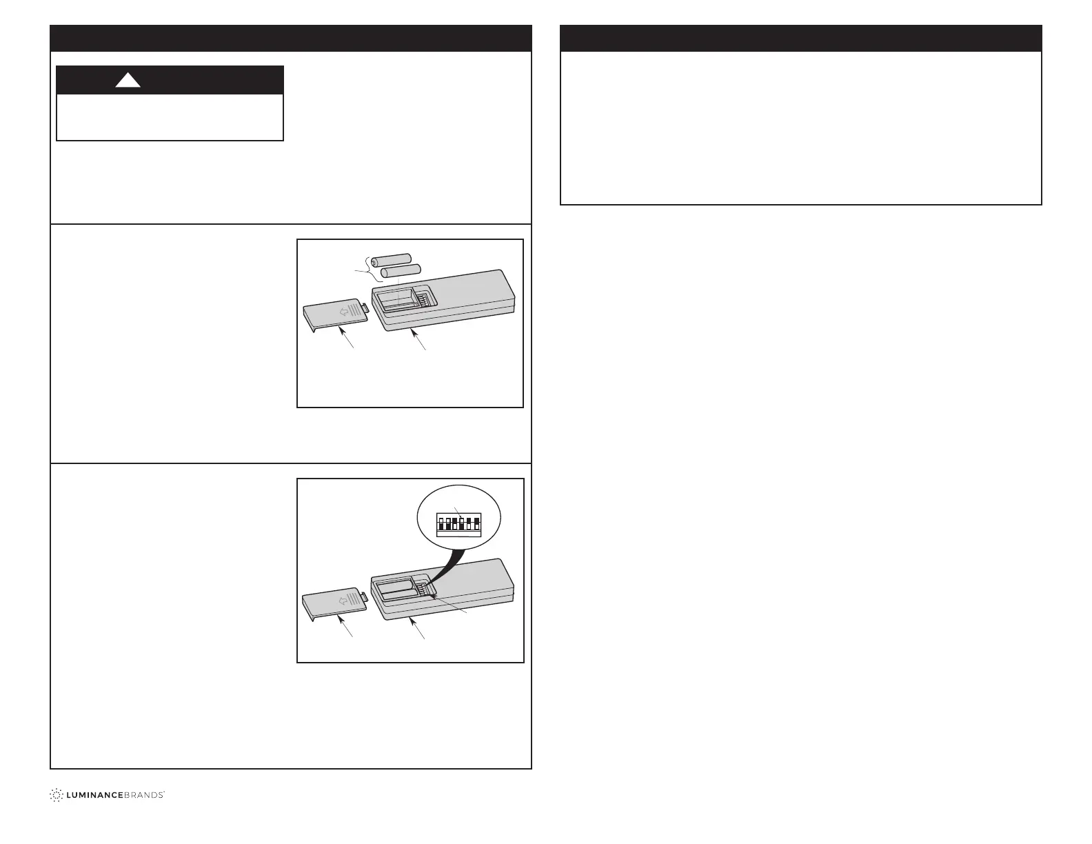
1.2: Installation of Batteries
1.
The Remote Control Transmitter is powered by
two AAA Alkaline Batteries.
2.
To prevent possible battery leakage damage, be
sure to remove the Batteries when the Control is
not to be used for an extended period of time.
3.
Remove the Battery Cover by pressing rmly
below the arrow and sliding the Cover off the
Remote Control.
4.
Install two new AAA Alkaline Batteries into the
Battery Compartment following the correct Battery
placement printed on the Compartment (Figure 1).
NOTE: Never use old and new Batteries together in
unit.
Figure 1
Your Receiver is equipped with a preset memory
feature. If the AC supply to the Receiver is powered
through a Wall Switch, when the Switch is turned
OFF, the Control will remember the Light Intensity
and Fan Speed.
When the Switch is turned back ON the light and fan
will resume operation as they were prior to the Switch
being turned OFF.
5. Replace the Battery Compartment cover by
sliding the Cover back onto the Remote Control.
REMOTE CONTROL
BATTERY
COMPARTMENT
COVER
TWO AAA
BATTERIES
1.3: Setting Frequency
5.
Remove the Battery Cover by pressing rmly below
the arrow and sliding the Cover off the Control
(Figure 2).
6.
Your Remote Control has Code Switches
which must be set in one of 32 possible code
combinations.
7.
The ve levers (numbered 1, 2, 3, 4, and 5) on the
switches are factory-set in the ON (up) position.
Change the Switch settings as follows:
8.
Slide the ve Switch Levers in the Remote Control
to your choice of ON (up) or down positions. Use a
ball-point pen or small screwdriver and slide the
Levers rmly up or down (Figure 2).
9.
The sixth Switch marked ON and I is for dimming
control of lights: Set Switch to ON to allow for
dimming of the lights. Set Switch to I for no
dimming of the lights.
NOTE: If your Fan and Light go on and off without
using your Control, you may be getting interference
from other remote units such as garage door openers,
car alarms or security systems.
To remedy this situations, simply change the
combination code in your Remote Control Transmitter.
CODE
SWITCHES
REMOTE CONTROL
BATTERY
COMPARTMENT
REMOTE CONTROL
LEVERS
ON
1
234
5
I
Figure 2
Troubleshooting
Fan/Light Fails to Operate
• Check that the speed control switch (if pull chain)
on the fan is set to HIGH speed.
• Check that the light switch (if pull chain) on the fan
is ON.
• Check that the battery is good (power indicator
light should light when any button is pressed).
• Check that the receiver is wired properly.
Short Range
• If the remote control operates the fan when close
to it, but does not operate it at a distance of
40 feet, try placing the antenna wire outside of the
ceiling cover.
 Loading...