6
Model No.: SR400/SR401
3
luminancebrands.com
Please contact 1-800-777-4440 for further assistance
Model No.: SR400/SR401
Receiver Installation
To avoid possible electrical shock, be sure
electricity is turned off at the main fuse box
before wiring.
NOTE: If you are not sure if the outlet box
is grounded, contact a licensed electrician
for advice, as it must be grounded for safe
operation.
WARNING
!
2.1
NOTE: Make all wiring connections using wire
connectors (supplied). Make sure that all
connections are tight, including ground, and that no
bare wire is visible at the wire connectors, except for
the ground wire.
1. After electricity has been turned OFF at main fuse
box or circuit breaker box, remove the ceiling
cover from the hanger bracket.
2. Disconnect the supply wiring to the fan by
removing wire connectors.
2.2:
(Figure 3)
3.
Securely connect the Receiver White Wire
(AC IN N) to the Supply White Wire (neutral)
using the 12 ga. Wire Connector, supplied.
4.
Securely connect the Receiver Black Wire
(AC IN L) to the Supply Black Wire (HOT) using
the 12 ga. Wire Connector, supplied.
5.
Securely connect the Receiver White Wire
(TO MOTOR N) to the Fan Motor White Wire
using the 18 ga. Wire Connector, supplied.
6.
Securely connect the Receiver Black Wire
(TO MOTOR L) to the Fan Motor Black Wire using
the 18 ga. Wire Connector, supplied.
7.
Securely connect the Receiver Blue Wire
(TO LIGHT) to the Fan Motor Blue Wire using the
18 ga. Wire Connector, supplied.
Check to see that all connections are tight
and that no bare wires are visible at the wire
connectors.
WARNING
!
NOTE:
Do not disconnect the green/bare ground
wires.
CAUTION: If no light exist on your ceiling fan, cap
the blue wire on the receiver with a wire connector.
NOTE: Failure to properly connect the receiver wires
will damage the device and render it non-operable
ANTENNA
RECEIVER
GND
SWITCH OR OPTIONAL
SW406 WALL CONTROL
BLACK
BLACK
WHITE
BLACK or RED
BLACK
WHITE
HANGER BALL
GREEN WIRE (GROUND) FROM
HANGER BALL AND HANGER
BRACKET
TWO-CONDUCTOR
CABLE
(WITH GROUND)
BLACK
(HOT)
WHITE
GROUND
TO
120-VOLT
SUPPLY
WHITE
BLUE
WHITE
BLUE
Figure 3
Remote Control Operation (Continued)
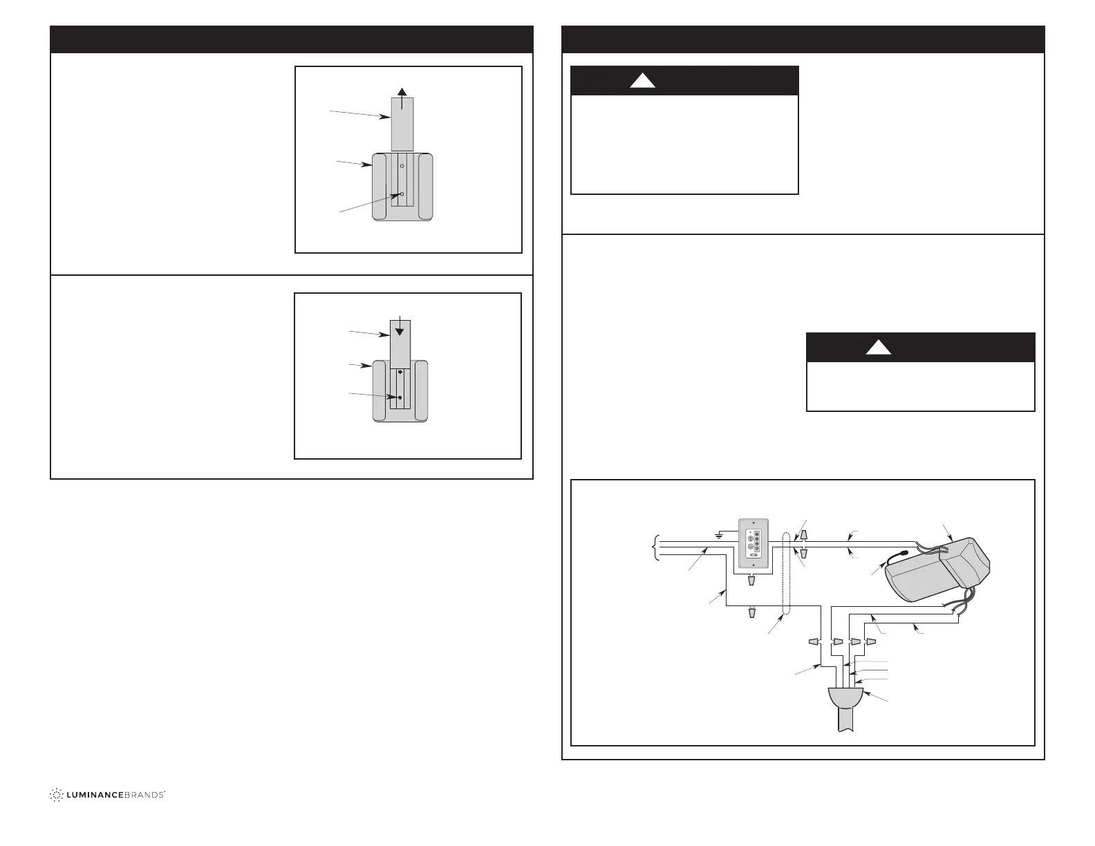
3.4: Storage Bracket Installation
1. Storage Bracket is provided for holding your
Remote Control when not in use. If you desire to
use the Bracket, install it on a Wall that is away
from excess heat or humidity.
2. Slide the Wall Bracket Cover up to expose the
Screw Holes for installation (Figure 8).
3. Position the Bracket on the Wall in desired
location.
Figure 8
3.5
4. Install the two Screws (provided with bracket)
into the Wall Bracket and tighten to secure to Wall
(Figure 9).
5. Slide the Wall Bracket Cover back down over the
Screws.
Refer to the Ceiling Fan Owner’s Manual to complete
this installation.
Figure 9
TO INSTALL BRACKET TO
WALL:
SLIDE THE COVER UP TO
EXPOSE THE SCREW
HOLES FOR INSTALLATION
COVER
WALL
BRACKET
SCREW
HOLES (2)
TO INSTALL BRACKET
TO WALL:
INSTALL THE TWO SCREWS
SLIDE THE COVER DOWN
WALL
BRACKET
SCREWS (2)
COVER
 Loading...