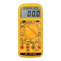
3)Select the " Function Switch" to the " RPM " position.
4)Connect the RPM INDUCTIVE PICK UP SENSOR to
the HIGH TENSION WIRE of No. 1 SPARK PLUG (or
No. 2, No. 3... SPARK PLUG), ref. Fig 2, then the display
will show RPM reading (x 10 RPM).
NOTE:
a. RPM (TACH) used the "Secondary Tech"
measuring method, no matter what cylinder is
b. If the display reading is unstable, it may be caused
by environment interference. Please readjust the
position of RPM INDUCTIVE PICK UP SENSOR
or changed the direction of INDUCTIVE
CLAMPS.