Do you have a question about the Lutron Electronics LCR-9184 and is the answer not in the manual?
Details general specifications like display size and test frequencies for the LCR meter.
Lists electrical specifications including resistance (DCR) and accuracy at various frequencies.
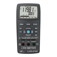
Describes the main display unit of the LCR meter.
Details the function of the frequency selection button on the front panel.
Explains the operation of the hold button for freezing readings.
Describes the button used to select L, C, or R measurement modes.
Explains the function of the calibration button.
Covers the ▲ button and RS232 interface button.
Details the < button and the D/Q/0 parameter selection button.
Explains the relative/percentage and down arrow buttons.
Describes the > button and the serial/parallel mode selection button.
Details the operation of the power on/off button.
Identifies the pin terminals for component connection.
Identifies the banana terminals for component connection.
Locates the input socket for the DC 9V power adapter.
Identifies the terminal for RS232/USB data output.
Mentions the stand for the device.
Refers to the screws securing the battery cover.
Describes the battery compartment and cover.
Explains the button to control the LCD backlight.
Details the function of the enter button.
Describes the button for sorting components.
Explains the setup button for configuration.
Outlines the basic steps for powering on and initiating measurements with the LCR meter.
Explains how to freeze and cancel the displayed measurement value.
Describes how the meter automatically selects serial or parallel mode based on impedance.
Details how to select different test frequencies for measurements.
Explains the relative measurement mode for comparing component values.
Describes the component sorting function based on tolerance and reference values.
Guides through the OPEN/SHORT calibration process to improve measurement accuracy.
Explains how to activate and deactivate the LCD backlight.
Details how to transmit measurement data to a PC via RS232.
Introduces the optional SMD tester (Model: SMDA-22) for component measurement.
Describes the optional SMD test clip (Model: SMDC-21) for testing SMD components.
| Brand | Lutron Electronics |
|---|---|
| Model | LCR-9184 |
| Category | Multimeter |
| Language | English |