EasyManua.ls Logo

Luverne 415254 - User Manual

Luverne 415254
2 pages
Print Icon
To Next Page IconTo Next Page
Loading...
LUVERNETRUCK.COM
NEED ASSISTANCE?
877.287. 8 63 4
570749-INS-RA
PAGE 1
INSTALLATION MANUAL
570749
Parts List
2 Mounting bracket, lower
2 Mounting bracket, upper
8 Hex head screw, 7/16"-14 x 4"
8 Flat washer, 7/16"
8 Hex nut, serrated flange, 7/16"-14
8 Hex head screw, 3/8"-16 x 1"
8 Flat washer, 3/8"
8 Hex nut, serrated flange, 3/8"-16
Torque Specifications
Metric
M6 bolt 3 ft-lbs.
M8 bolt 7 ft-lbs.
M10 bolt 16 ft-lbs.
M12 bolt 28 ft-lbs.
SAE
1/4" bolt 3 ft-lbs.
5/16" bolt 7 ft-lbs.
3/8" bolt 16 ft-lbs.
7/16" bolt 20 ft-lbs.
1/2" bolt 28 ft-lbs.
Use above torque setting unless otherwise noted
Tools Required
Socket set --
Level of Difficulty
Easy
Notes and Maintenance
Before you begin installation, read all instructions thoroughly.
Proper tools will improve the quality of installation and reduce the time required.
Mild automotive detergent may be used to clean the product. Do not use dish detergent, abrasive
cleaners, abrasive pads, wire brushes or other similar products that may damage the finish.
Refer to the table to the left when securing hardware during the
installation process to help prevent damage to the product or vehicle.
Product Photo
Grip Step
Running Boards
(not included)
Product Registration
CURT Group stands behind our products with industry leading warranties.
You can help us continue to improve our product line and help us understand
your needs by registering your purchase by visiting:
warranty.curtgroup.com/surveys
At CURT Group, customer is king. We value your feedback and we use that information to make
improvements on our products. Please, take a minute and let us know how we are doing.
Upper
Lower
This is the first of two manuals
required to complete this installation.
The second manual is included with
your running boards / side steps.
Question and Answer IconNeed help?

Do you have a question about the Luverne 415254 and is the answer not in the manual?

Summary

Notes and Maintenance

Product Registration

ASSEMBLY

Step 1: Driver Side Mounting

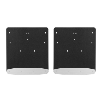
Install the upper mounting bracket on the driver side rear frame using 7/16" hardware. Tighten to 19 ft-lbs.

Step 2: Lower Bracket Installation

Install the lower mounting bracket using 3/8" hardware. Snug hardware but do not fully tighten.

Step 3: Passenger Side Installation

Repeat steps 1 through 3 for the passenger side of the vehicle.

Step 4: Running Board Attachment

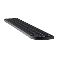
Attach the running board according to its specific instructions. Snug hardware but do not fully tighten.

Step 5: Final Tightening

Ensure the step is level and positioned correctly, then tighten all remaining bolts to 19 ft-lbs.

Overview

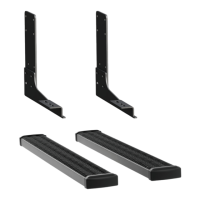
This document provides installation instructions for Luverne running board mounting brackets, designed to facilitate the attachment of Grip Step™ running boards or similar side steps to a vehicle. The manual is one of two required for a complete installation, with the second manual included with the running boards themselves. The installation process is rated as "Easy" in terms of difficulty.

Function Description

The primary function of this device is to provide a secure mounting point for running boards or side steps on a vehicle's frame. It consists of upper and lower mounting brackets that attach to the vehicle's rear frame, creating a stable platform for the running boards. The system is designed to be robust, using various bolts, washers, and nuts to ensure a strong connection that can withstand the forces associated with stepping on and off the vehicle. The brackets are specifically engineered to integrate with Luverne's Grip Step™ running boards, as well as MegaSteps® or O-Mega Steps™, offering flexibility in the choice of side steps.

Usage Features

The installation process is straightforward, outlined in a step-by-step manner to guide the user through attaching the mounting brackets to the vehicle.

  • Step 1: Upper Mounting Bracket Installation (Driver Side)

    • The first step involves locating the mounting holes on the driver side rear frame.
    • The upper mounting bracket is secured using four 7/16"-14 x 4" hex head screws, four 7/16" flat washers, and four 7/16"-14 serrated flange nuts.
    • All hardware should be tightened to 19 ft-lbs, ensuring a firm initial connection.
  • Step 2: Lower Mounting Bracket Installation (Driver Side)

    • Following the upper bracket, the lower mounting bracket is installed.
    • This is done using four 3/8"-16 x 1" hex head screws, four 3/8" flat washers, and four 3/8"-16 serrated flange hex nuts.
    • During this step, the hardware should only be snugged, not fully tightened, to allow for adjustment.
    • A crucial note for this step concerns the positioning of the lower bracket based on the type of running board being installed:
      • For Grip Steps™, it is recommended that the lower bracket be positioned all the way out and mounted in the lower set of holes.
      • For MegaSteps® or O-Mega Steps™, the lower bracket should be slid all the way in and mounted in the upper set of holes. This adjustability ensures proper fitment and alignment with different running board designs.
  • Step 3: Passenger Side Repetition

    • Steps 1 and 2 are then repeated for the passenger side of the vehicle, ensuring symmetrical installation of the mounting brackets.
  • Step 4: Running Board Attachment

    • Once both sets of brackets are installed, the running board itself is attached according to the instructions provided in the separate step board manual.
    • Similar to Step 2, the hardware for attaching the running board should only be snugged at this stage, allowing for final adjustments.
  • Step 5: Final Tightening and Adjustment

    • The final step involves ensuring that the running board is level and correctly positioned.
    • Once satisfied with the alignment, all remaining bolts are tightened to 19 ft-lbs, securing the entire assembly firmly to the vehicle.

The manual includes a detailed parts list, specifying the quantity and description of each component required for the bracket installation. This includes:

  • Two lower mounting brackets
  • Two upper mounting brackets
  • Eight 7/16"-14 x 4" hex head screws
  • Eight 7/16" flat washers
  • Eight 7/16"-14 serrated flange hex nuts
  • Eight 3/8"-16 x 1" hex head screws
  • Eight 3/8" flat washers
  • Eight 3/8"-16 serrated flange hex nuts

Tools required for installation are a socket set, indicating that common automotive tools are sufficient.

Maintenance Features

The manual provides important notes regarding maintenance and care of the product to ensure its longevity and appearance.

  • Cleaning: Mild automotive detergent is recommended for cleaning the product. It explicitly advises against using harsh cleaning agents such as dish detergent, abrasive cleaners, abrasive pads, wire brushes, or similar products that could damage the finish. This guidance helps preserve the aesthetic quality and protective coating of the brackets.

  • Torque Specifications: A comprehensive table of torque specifications is included for various bolt sizes (M6, M8, M10, M12, 1/4", 5/16", 3/8", 7/16", 1/2"). This table is crucial for proper installation, as applying the correct torque prevents over-tightening (which can strip threads or damage components) and under-tightening (which can lead to loose connections and potential failure). The manual emphasizes using these torque settings unless otherwise noted, highlighting their importance in preventing damage to both the product and the vehicle during installation.

  • Product Registration: Users are encouraged to register their purchase through the provided website (warranty.curtgroup.com/surveys). This feature serves multiple purposes:

    • It helps CURT Group, the manufacturer, to stand behind their products with industry-leading warranties.
    • It allows the company to gather feedback and understand customer needs, which contributes to improving their product line.
    • It fosters a customer-centric approach, as CURT Group values customer feedback for product improvements.

Overall, the manual is designed to be user-friendly, providing clear instructions, necessary component lists, and essential maintenance tips to ensure a successful installation and long-term satisfaction with the product.

Luverne 415254 Specifications

General IconGeneral
MaterialAluminum
Step Quantity2
Model Number415254
BrandLuverne
FinishBlack

Related product manuals