Operating Instruction
Q5.25.45
TLT Page
15 / 18
Draft created/changed: 31.01.03/TT Document created/changed: 03.08.2012 / Rea
Revision: - Revision: -
Draft released: 18.02.03/DEL Document released: 03.08.2012 / Rea
Jede unerlaubte Verwendung ist strafbar / Any unpermitted use is subject to prosecution.
7
7
.
.
7
7
O
O
f
f
f
f
s
s
e
e
t
t
a
a
d
d
j
j
u
u
s
s
t
t
m
m
e
e
n
n
t
t
f
f
o
o
r
r
a
a
n
n
a
a
l
l
o
o
g
g
u
u
e
e
o
o
u
u
t
t
p
p
u
u
t
t
:
:
With this function, the analogue output and the value for manual output can be adjusted
from -5%RH to 105%RH. This allows an adaption to inaccurate analogue inputs.
7.7.1 Settings before correction
Adjust the desired values for Range L and Range H at the Transmitter HTT-V,
for example 0%RH (RLs) and 100%RH (RHs).
Set the desired output range (0/2..10V, 0/4..20mA).
Set the control system in the same way.
7.7.2 Measurement
Enter a manual value for example 10%RH (S1). Note the range on the control system, e.g. 11%RH (M1).
Enter a manual value e.g. 90%RH (S2). Note the range on the control system e.g. 92%RH (M2)
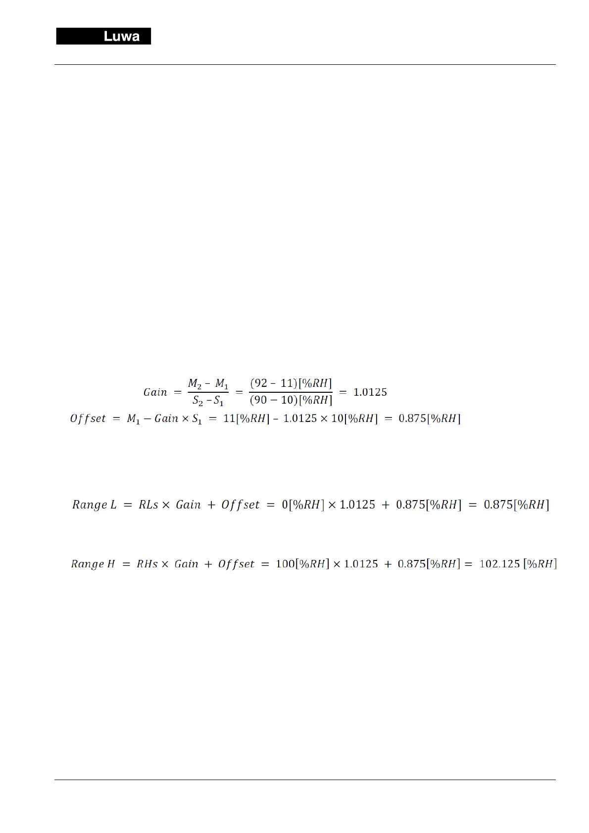
7.7.3 Calculation Gain and Offset
7.7.4 Calculation corrected settings Range L and Range H
To adjust 0.9[%RH]
To adjust 102.1[%RH]
The display on the control system should now concur with the one on the transmitter. The linearity of both sys-
tems is assumed.
Should the deviation at the nominal value of the measurement of the system be too big due to a nonlinearity,
chose for S
2
a value around the nominal measuring value and for S
1
the RLs value.
 Loading...