Operating Instruction
Q5.25.45
TLT Page
9 / 18
Draft created/changed: 31.01.03/TT Document created/changed: 03.08.2012 / Rea
Revision: - Revision: -
Draft released: 18.02.03/DEL Document released: 03.08.2012 / Rea
Jede unerlaubte Verwendung ist strafbar / Any unpermitted use is subject to prosecution.
5
5
M
M
O
O
U
U
N
N
T
T
I
I
N
N
G
G
1. First remove the bottom of the instrument. If necessary, 4 holes can be broken through for the mounting on
the wall or at the ventilation duct. The breakthroughs should remain closed when assembling it at a ventilation
duct through cable flanges. This is the only way to guarantee the housing tightness
2. In case of unevenness of the mounting wall, 4 spacers can be assembled.
3. Insert the appropriate cables into the membrane which is at the bottom of the instrument by piercing small
holes into the membrane with a pointed scriber and then push the cables (only simple isolation) through the
holes.
4. Please use the stain relief plate for a cable stain relief.
5. After having set the dowels or drilled the appropriate holes in the wall, the bottom can be screwed.
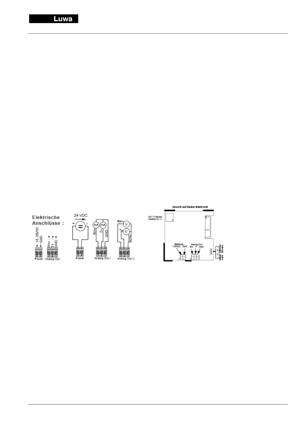
6. Now you can screw the cables on the connector with the ferrule. Please consider for this the electric diagram
of the designer, respectively of the instrument.
7. Check the wiring carefully, before connecting the plugs to the cover plate with integrated electronics.
8. Introduce the cover plate into the upper bracket and click it laterally on the bottom. Check the correct fitting.
9. After switching on the supply voltage the HTT-V registers on the display.
EMC note:
1. Disturbing circuits of measurement or analysis units have to be separated by open ground.
2. Avoid, wherever possible, the parallel motion of measurement connections and power electric cables.
3. Shield the measurement connections, if necessary, and connect the screen only on one side with a defined
mass potential.
4. Twist the unshielded cables in pairs and keep them as short as possible.
Recommended cabling:
Supply: 24 VDC +/- 10% single-strands from 0.5...0.75 mm2 (22 ... 18 AWG) with PVC insulation or equivalent 2-
fold strand.
AOUT: 0...10 VDC / 0... 20 mA
Single-strand from 0.25...0.5 mm2 (24 ... 20 AWG) twisted and possibly shielded with PVC insulation or corre-
sponding 2/3/4-fold strand.