These units are designed to operate with clean water at a maximum water temperature
of
50
°
C.
Built of top quality materials, they are subjected to strict hydraulic and electrical contrais and
are carefully verified .
Correct installation
is
ensured by following these instructions and those
of
the wiring diagram;
otherwise, over loads may be produced
in
the motor. We decline responsibility for any
damage caused
by
not following these instructions.
2.lnstallation
The pumps should be installed horizontally, securing them with screws through
ITJ
the hales
in
the supports to prevent undesirable noise and vibration.
The suction, pipe of the pump should
be
as short as possible.
The rating Label must be visible after installation. Parts coutaining live parts, except parts
supplied with safety extra low voltage<12V, must
be
inaccessible to a persan
in
the SPA.
Glass
1 appliances must be permanently connected to fixed wiring . Part including
electrical components except remote contrai devices must be located or fixed
so
that they
cannot into SPA.
3.Pipe
Assembly
The suction and discharge pipes should have a diameter equal to or greater than that of the
intake tapping of the pump.
Avoid traps as,
in
addition to affecting efficiency, they impede total overall emptying.
The suction and discharge pipes should not rest
on
the pump in any case.
Seal all the connectors and unions well. Avoid any dripping on the motor, which would
unfailingly damage
it.
4.Electrical
connection
The electrical install action should have a multiple separation system with contacts opening
&,
at least 3mm.
For continued protection against possible electric shock this unit
is
to
be
mounted
Io
the base
in
accordance with the installation instructions.
The protection of the system should be based
on
a residual current device (RCD) with a
rated tripping current no! exceeding 30mA. The supply cable should comply with EMC
standards (2).Single-phase motors have built-in thermal protection. The electric connection
must be carried out by qualified staff following strictly the "EN60335-2-60" standard.
Be
sure that the earth cable connection is correctly made.
Be
sure that the equipotential connection between the bath and the pump is correctly made.
Wires serving as equipotential bonding conductors shall have a cross sectional area between
2.5 and 6mm
2
and shall
be
equipped with the terminal suitable receptacle.
5.Controls
Prior
to
Initial
Start-up
A Verify that the pump shaft turns freely.
Check that the mains voltage and frequency are according to the name plate.
The hydromassage assembly should be equipped with a system to prevent the pump from
starting up if a minimum water level is not present.
Check the rotating direction of the motor, which should concur with that indicated
on
the fan
caver.
If the motor does no! start up, try to locale the problem
in
the table
of
most common faults
and their possible solutions that is provided further on.
THE PUMP SHOULD NEVER OPERATE DRY.
-2-
6.Start·up
Start electrically
the
pump
only
when
the
suction
and
discharge
pipes
are
connected
Io
the
corresponding inlets
and
outlets.
Check
that
there
is
no
obstacle
in
the
pipes.
Apply
voltage
to
the
motor
and
suitably
adjust
the
jets
to
obtain
the
desired
flow.
7.Maintenance and clean
Before
maintenance
and
cleaning,
please
make
sure
that
the
power
supply
must
be
eut-off.
DJ
Our
pumps
for hydromassage facilities
do
no!
require
any
special
maintenance
or
programmir
If
the
pump
will
be
idle
for a
long
period
of
time
,
it
is
recommended
to
disassemble,
clean
an
store
il
in
a
dry,
well-ventilated
place.
If
the
supply
cord
is
damaged,
it
must
be
replaced
by
the
manufacturer
or
its
service agent
or
a similarly qualified
persan
to
a
hazard.
Pump
can
be
automotive
empty
water after correct installation.
When
the
pump
needs
to
clean
(1)
filling
with
water
up
Io
level
position
of bathtub's
nozzle,
(2)
operati1
2-3mimute,(3) exhausting water of
SPA
after
engine
stop.
8.Trouble
Shooting
Guide
SYMPTOM
POSSIBLE
CAUSE
CHECK
-incoming
power
to the pump?
NO
POWER
-ls
circuit
breaker
on?
PUMP
DOES
TO
PUMP
-ls
GFCI
operating
properly?
-ls
the
air
switch plugged in?
NO
TURN
-ls the air switch hase connected
to
the pump?
AIRSWITCH
-ls the air switch hase connected
to
the actuator
DISCONNECTED
button
on
the tub deck?
-Jets should
be
pointed away from the suction
PUMP
NOT
BLOCKAGE
OR
inlet
so
air is not forced into pump suction
-ls the in-tub suction inlet blocked
or
covered?
PUMPING
LEAK
-ls there any debris
in
the pump housing?
PROPERLY
-ls there a leak
in
the piping or the pump?
LOW
VOLTAGE
-ls
the
proper
voltage
applied
Io
the
pump?
-ls
there
an
extension
cord being used?
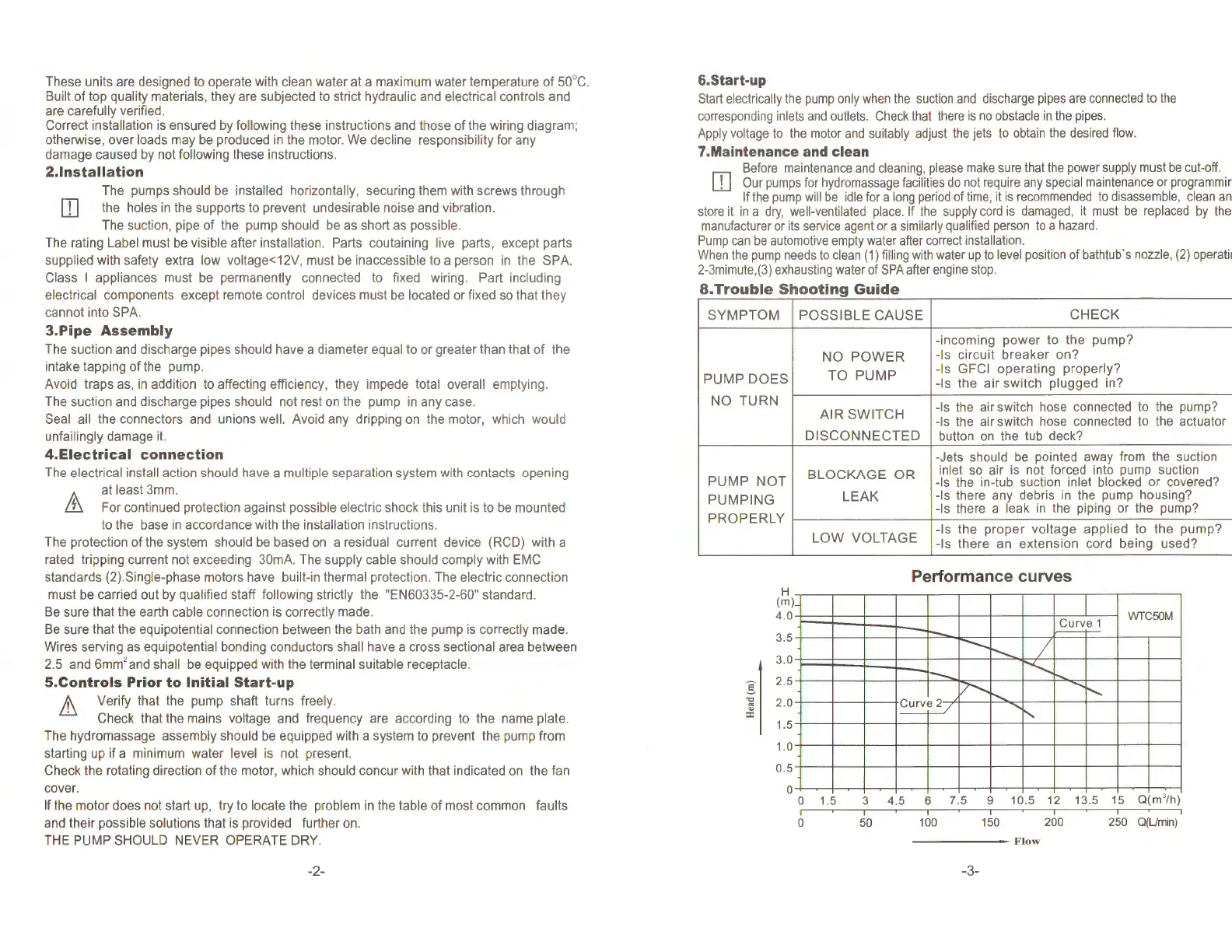
Performance curves
Il
H
(m)
4.0
i::==
. '
3.5
,_,
3.0
.
_,
2.5
2.0
~
·-'
1.5
1-
1.0
J__
0.5
0
1
0 1.5
1
l
1
1
-+---1
1
1
-
+--~
1
Curve
1
WTC50M
-....
t-..
/
1
1
-+---
r--,_
..............
....
1
17"--
-
I~
"'-.
.......
.....
r---
-
1
1
1
1 1
1
1
1 1
1 1
1
1
-
1 1 1 1
3
4.5
6
7.5
9
10.5
12
13.5
15
Q(m
3
/h)
1 1 1
0 50 1
OO
150 200 250 Q(Umin)
--------
Flow
-3-
 Loading...