Do you have a question about the Lycoming TEO-540-A1A and is the answer not in the manual?
Defines the letters and numbers in the engine model nomenclature.
Details the manual's content and purpose for Lycoming engines.
Explains how Lycoming provides timely updates via SBs, SIs, and SLs.
Emphasizes operating the engine according to manual specs and other service documents.
Explains the importance of safety advisories and their definitions.
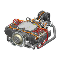
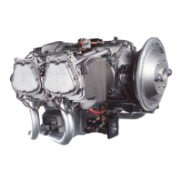
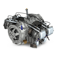
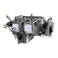
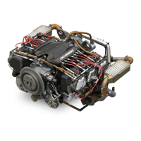
Describes the TEO-540-A1A engine as a turbocharged, electronically-controlled, six-cylinder unit.
Explains the EECS as a microprocessor system for monitoring and adjusting engine parameters.
Details the primary components (ECU, Power Box, ADL) and secondary components of the EECS.
Describes the FST as diagnostic software for identifying fault codes and monitoring ECU operation.
Explains how the EECS controls actuators, spark plugs, fuel flow, and engine speed.
Details the EECS input power requirements and airframe interface connection.
Describes the two types of wiring harnesses: engine-to-firewall and airframe interface.
Lists sensors connected to harnesses that measure engine parameters for ECU input.
Describes the components within each of the six engine cylinders.
Details the construction of the crankcase and its role in housing components and oil passages.
Describes the flange-type propeller shaft and its attachment to the crankshaft.
Explains the engine fuel system components including pump, filter, injectors, and manifold.
Details the ignition system, including harness, coils, spark plugs, and power sources.
Describes the air induction system, its components, and requirements for air cleaners.
Explains the function of the two turbochargers and the EECS control.
Describes the accessory housing and the types of accessory drive pads.
Lists the components of the wet sump pressurized lubrication system.
Discusses the engine mounting brackets and rear Dynafocal mounting.
Illustrates cylinder numbering and the engine firing order.
Details the EECS functions including performance increase, fuel adjustment, and fault detection.
Explains the sequence of events for EECS to start and operate the engine.
Defines engine synchronization as the calculation of crankshaft and camshaft speed.
Describes how the EECS controls fuel injection and air/fuel ratio.
Explains how the EECS electronically controls ignition timing and spark plug operation.
Details the redundant methods the EECS uses to calculate engine airflow.
Explains how the EECS identifies and disables non-operational cylinders.
Describes EECS monitoring and adjustment of Cylinder Head Temperature (CHT).
Explains EECS adjustment of fuel to control turbocharger turbine inlet temperature.
Details EECS control of the exhaust bypass valve and manifold pressure.
Explains EECS automatic control of propeller pitch for hydraulic constant-speed propellers.
Differentiates between engine overhaul and factory rebuild processes.
Explains how the EECS records operating time and that it cannot be reset.
Identifies pilot controls for the TEO-540-A1A engine and shows cockpit controls.
Describes EECS hardwired warning annunciators and their pilot actions.
Provides steps for safely removing the engine from its shipping container.
Outlines the steps for verifying the engine serial and model numbers upon receipt.
Refers to procedures for removing preservative oil from cylinders and crankcase.
Provides instructions and cautions for safely lifting the engine using straps.
Provides an overview of installation requirements and refers to an ICD.
Details the preparation steps for new, overhauled, rebuilt, or stored engines.
Outlines the depreservation procedure for engines prior to installation.
Instructions for preparing an engine that has been in storage for installation.
Lists items the airframe manufacturer must supply for initial engine installation.
Procedure for temporarily removing components to facilitate engine installation.
Instructions for installing engine mounting brackets, including inspection.
Refers to Table 1 for steps and section references for engine installation.
Details the procedure for installing the Engine Control Unit (ECU) with correct serial numbers.
Describes the installation of the Power Box, including its configuration and mounting.
Provides instructions for aligning and securing the engine to the airframe mounts.
Guides the connection of engine and airframe wiring harnesses, checking for damage.
Instructions for connecting the cable to the engine's power control linkage.
Instructions for installing external accessories onto the engine's accessory drive pads.
Details the installation of alternators and alternator belts as per maintenance manual.
Instructions for installing the propeller according to manufacturer specifications.
Guides the connection of fuel hoses, emphasizing cleanliness and proper routing.
Provides instructions for connecting oil hoses, ensuring smooth routing and proper torque.
Details the installation of ground straps for EECS operation and lightning protection.
Instructions for reinstalling removed components and any loose parts shipped with the engine.
Guides the final engine connections for wiring, accessories, ducts, and pipes.
Instructions for installing baffling around the engine compartment.
Details the procedure for adding the correct quantity and viscosity of oil to the engine.
Explains the critical pre-oil procedure to circulate oil and ensure pressure before starting.
Instructions for adding the specified fuel to the aircraft.
Notes the absence of a mechanical tachometer drive and the need for airframe calibration.
Directs the user to complete the Engine Installation Checklist.
Instructions for closing the engine compartment, ensuring no tools are left behind.
A checklist to ensure all engine installation steps have been completed correctly.
Steps for preparing the aircraft and engine for a ground operational test.
Details the procedure for conducting the ground operational test of the engine.
Outlines procedures for initiating newly installed or overhauled Lycoming engines.
States warranty conditions requiring adherence to manual specifications and maintenance procedures.
Guides the completion of a pre-flight inspection checklist for engine initiation.
Refers to the Pilot’s Operating Handbook for the daily pre-start inspection.
Provides a step-by-step procedure for starting the engine safely.
Details the procedure for conducting the operational test of the engine.
Guides the procedure for running up the engine, checking oil temperature and pressure.
Explains the pre-flight test (PFT) to ensure correct engine operation and EECS functionality.
Provides the procedure for safely shutting down the engine, including turbocharger cool down.
Outlines the engine break-in process, including flight tests and 50-hour operations.
Lists required inspections during the first 50 hours of engine operation.
Lists the prerequisite steps that must be completed before routine engine operation.
Refers to the POH for pre-start checks and notes on air filter inspection.
Details the engine start procedure, including safety checks and environmental considerations.
Guides the procedure for running up the engine, checking oil temperature and pressure.
Explains the pre-flight test (PFT) to ensure correct engine operation and EECS functionality.
Provides instructions for normal engine operation, including take-off and flight recommendations.
Details the procedure for safely shutting down the engine, including turbocharger cool down.
Explains how to use the Field Service Tool (FST) for fault isolation.
Describes how the EECS collects fault code data for diagnostics.
Identifies corrective actions for various engine conditions and annunciator states.
Provides procedures for starting an engine in cold weather conditions.
Offers Lycoming's recommended procedure for cold weather engine starts.
Provides recommendations for operating the engine in hot weather conditions.
Advises against operating in volcanic ash and outlines standard actions for contamination.
Explains engine overspeed conditions, EECS response, and corrective actions.
Discusses causes of low oil pressure and the recommended actions for a safe landing.
Explains how to prevent engine corrosion through regular operation and proper storage.
Details the procedure for preserving engines installed in aircraft stored for 31 to 60 days.
Refers to Service Instruction SI-1481 for preserving engines for longer periods.
Refers to fuel injector manufacturer's instructions for preservation.
Presents detailed specifications for the TEO-540-A1A engine.
Lists the operating limits for engine oil pressure, temperature, and consumption.
Shows accessory drives, their types, rotation, and torque specifications.
Lists physical environmental limits for EECS components as per DO-160F.
Displays critical safety alert messages and their corresponding titles and warnings.
Directs users to Appendix B of the Maintenance Manual for wiring details.
| Rated Speed | 2700 rpm |
|---|---|
| Compression Ratio | 8.7:1 |
| Fuel Type | AvGas 100LL |
| Oil System | Wet sump |
| Cooling System | Air cooled |
| Redline | 2700 rpm |
| Displacement | 540 cu in (8.8 L) |
| Bore | 5.125 in (130.2 mm) |
| Stroke | 4.375 in (111.1 mm) |
| Ignition System | Dual magnetos |
| Fuel System | Fuel injection |
| Fuel Grade | 100LL |
| Type | Horizontally Opposed, 6-Cylinder, 4-Stroke |