Page 14
Pulse Count
Pulse 1
Pulse 2
Pulse 4
x. In the Control Unit, against each of the two PIR connection terminals (zone =1, =2, =3 or zone =4),
there is a 3-position (0,1,2) slide switch. These switches are factory pre-set at position “0” when no
PIR is connected. When connecting one piece 2-wire PIR to the zone, you need to set the
corresponding switch to position “1”. When connecting 2 pieces 2-wire PIR to the same
zone
terminals, put the corresponding switch to position “2”. The wiring to connect two pieces 2-wire
PIR to one same zone terminals
are as page 17.
3.15 Installing Wired Movement Detector/PIR
(available separately as an accessory)
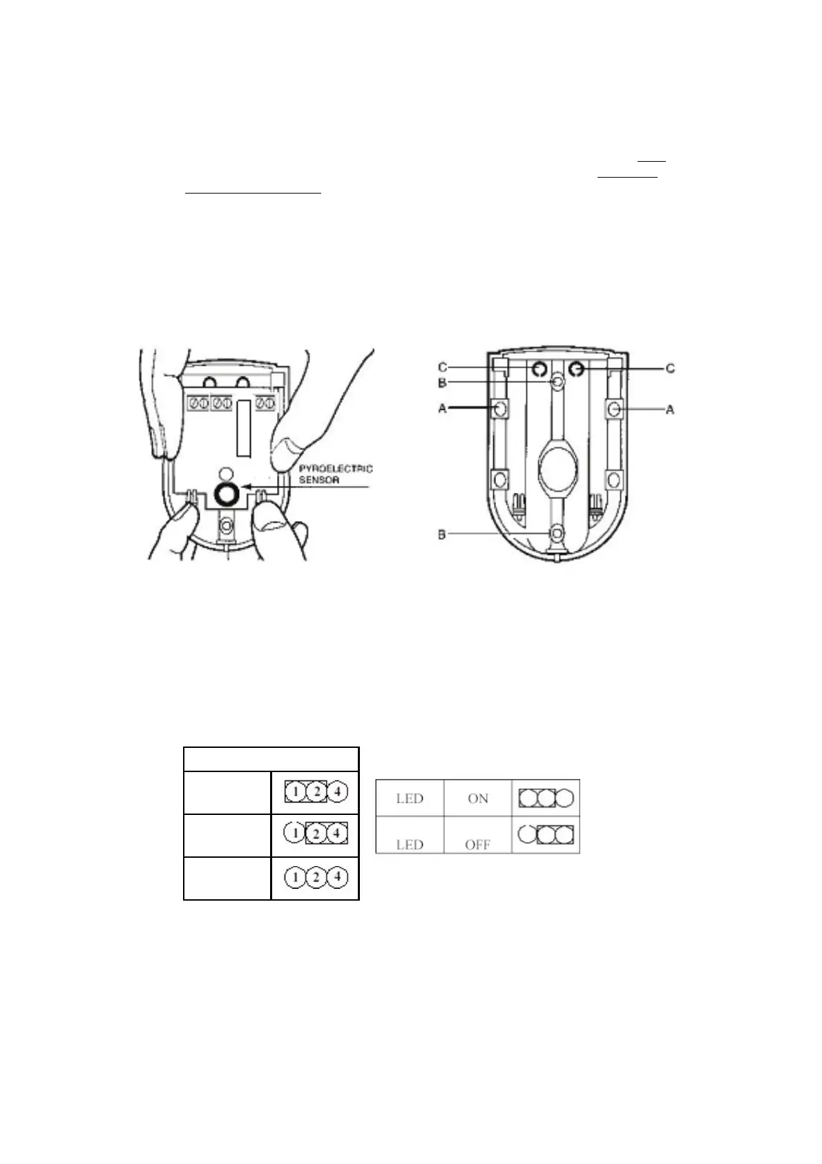
i. Remove and retain the screw from the bottom of the PIR and lift off the cover.
ii. Carefully remove the electronic module from its retaining clips, ensuring not to touch the
pyroelectric sensor (Illustration16)
Illustration 16 1llustration 17
iii. Use mounting points “A”, if you are fitting the detector in a corner. Use mounting points “B”, if
you are fitting the detector on a flat surface. Use a small drill to create two fixing holes at the
mounting points (Illustration 17).
iv. Hold the base of the PIR in the chosen position, ensuring that the front of the PIR will face
towards the center of the protected area, mark and drill two fixing holes in the wall. Choose one
of the cable entry holes “C” and make a third hole in the detector base. Put one end of the 2-core
wire through this hole “C”, then secure the PIR to the wall using two screws and wall plugs
provided.
v. Replace the electronic module into the retaining clips, ensuring that it is correctly positioned and
firmly seated.
 Loading...