Page 15
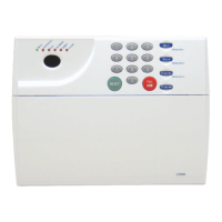
vi. If required, select the PIR LED “ON” or “OFF” option and the sensitivity (pulse count) by
setting the corresponding jumpers on the electronic module. Note that Pulse 1 option is more
sensitive than the pulse 4 option. Pulse 1 option is used when it is necessary to activate an alarm
on the first detected pulse, or in high security installations – where fast “catch” performance is
of greatest importance. Pulse 2 or 4 settings provides improved protection against false alarms
caused by all types of environmental disturbances. (Illustration 18)
Illustration 18
vii. Run the cable back to the Control Unit, fixing the cable with cable clips and enter the wire into
the back of the Control Unit through any convenient cable hole.
viii. Replace the electronic module into the retaining clips, ensuring that is correctly positioned and
firmly seated.
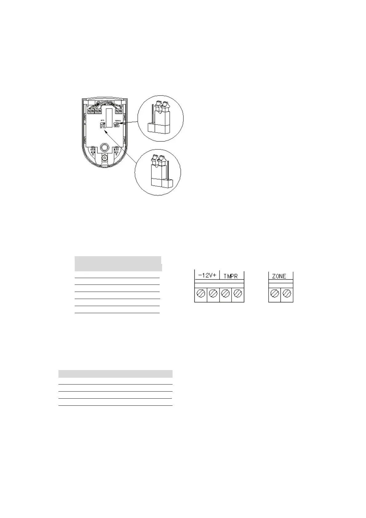
ix. Connect the 6-core cable to terminal block of the PIR. Use following wiring sequence:
CONNECTED COLOUR
TO USED
12V+ RED
12V- BLACK
TAMP GREEN
TAMP YELLOW
ZONE WHITE
ZONE BLUE
x. Run the cable back to the Control Unit, fixing the cable at the intervals of about 50cm using the
clips provided, and enter the wire into the back of the Control Unit through any convenient
cable hole.
xi. Select to which zone the PIR is to be connected and remove the jumper wire from the required
zone terminals.(Note: wired zone 1(d1) is an entry/exit zone). Make connections to the Control
Unit terminals as follows (Wiring diagram 2).
CONTROL UNIT PIR COLOUR
AUX 12V+ 12V+ RED
AUX 12V- 12V- BLACK
ZONE ZONE WHITE
ZONE ZONE BLUE
N.B. Observe polarity on 12V terminals. The PIR ZONE and Control Unit Zone terminals are not
polarized.
In order to insert the PIR into the Tamper Circuit, the two wires which have been connected to the
Tamper Terminals in the PIR, yellow and green, must be wired to the Terminal Strip (Wiring Diagram
2). Remove one of the wires links from the Terminal Strip and connect the yellow and green wires in its
place. The wiring connection is as the wiring diagram on page 18.
xii. Replace cover on PIR and refit the retaining screw.
FRAME
 Loading...