CARE & USE/INSTALLATION
|
15
Gas connections will vary depending on heater mounting
location selected and the gas type (NG or LP) being used.
See also previous section ‘Gas Supply and Connections’.
Prior to mounting the heater, the gas connections were
considered and an overall routing ‘plan’ was established.
A minimum pipe size of ½” is required for inlet piping. The
supplied exit coupling of this heater is ½”FIP (female). A
½” leaver- handled manual gas shut-off valve should be
installed within 6 feet of the appliance to allow emergency
gas shut-off and provide isolation for servicing.
With the exception of flared fittings, all gas pipe
connections to the heater must be sealed with gas pipe
compound or Teflon sealing tape. Prior to use, the gas
supply line should be checked for leaks by applying a mild
solution of soap and water. Never use an open flame to
check for leaks. See section titled ‘Checking for Gas Leaks’,
page 17.
Run the gas line to the vicinity of the heater. It is
recommended that the gas line be securely fixed to the wall
or mounting surface. WARNING: do not run gas line in a
location that it can be tripped over or in a location that
passes by either the heat output or the exhaust of the
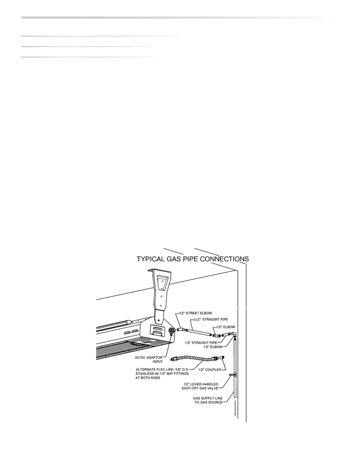
heater. This gas line can now be attached directly to the
heater using a series of elbows and short sections of straight
pipe (nipples), sufficient to lead gas piping from the wall to
the inlet of the heater. The final fitting will be a ½”NPT male
pipe to mount directly into the heater. A 30” Stainless Steel
flexible line ½” I.D. (5/8” O.D.) with ½” MIP (male) fittings at
both ends. A ½” FIP (female) coupling would then be used
to connect the flex line to the hard pipe.
Please note that when gas is hard piped, an external
gas-pressure regulator is not required as the heater is
equipped with an internal, built-in gas-pressure regulator as
part of the gas control valve.
An alternative to the hard pipe installation (NG or LP) is to
use a metal flex hose which mounts directly from the main
gas source and extends directly into the heater inlet. See
illustrations below for installation techniques.
GAS CONNECTIONS
MAKING THE GAS CONNECTONS