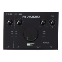
[MIUFc] AIR 192|6 Test App v1.0.5 procedure
Test App
1. Input Gain
2. LED Meters
3. USB / Direct Blend
4. Headphone Level
5. Monitor Level
6. Power LED
7. +48V (Phantom Power) LED
8. MIDI In LED
9. MIDI Out LED
MIDI IO Test
1. Using a 5 pin MIDI cable, connect the MIDI output port to the MIDI input port.
2 Press the START TEST button.
Audio test
Audio test #1
1. Using 2 qty 1/4" TRS cables.
2. Connect Main OUT L channel to Rear Input 1.
3. Connect Main OUT R channel to Rear Input 2.
4. Set Main Volume (knob #5) to Max.
5. Set all Gain knobs (knob #1) to Min.
6. Monitor Knob (knob #3) to full USB
Audio test #2
1. Using 2 qty 1/4" TRS cables.
2. Connect Main OUT L channel to Rear Input 1.
3. Connect Main OUT R channel to Rear Input 2.
4. Set Main Volume (knob #5) to Max.
5. Set all Gain knobs (knob #1) to Max.
6. Monitor Knob (knob #3) to full USB
Audio test #3
1. Using 1 qty 1/4” TRS to 2 x 1/4" TS cables
2. Connect Headphone Out left channel to Front Input 1 and the right channel to Front Input 2.
3. Set Main Volume Max.
4. Set all Gain knobs to Min.
5. Monitor Knob to full USB
6. Set headphone Volume (knob#4) to Max.
Audio test #4
1. Using 1 qty 1/4” TRS to 2 x 1/4" TS cables
2. Connect Headphone Out left channel to Front Input 1 and the right channel to Front Input 2.
3. Set Main Volume Max.
4. Set all Gain knobs to Max.
5. Monitor Knob to full USB
6. Set headphone Volume (knob#4) to Max.
+48V Phantom Power Test
1. Switch the +48V phantom power to the right (turning it on).
2. Confirm that 48V is present on pins 2 and 3 of each XLR jack using the multimeter.
3. The acceptable pass range is 45V to 52V.
4. Switch the +48V phantom power to the left to shut down phantom power function.
 Loading...