M3LU
5-2-55, Minamitsumori, Nishinari-ku, Osaka 557-0063 JAPAN
Phone: +81(6)6659-8201 Fax: +81(6)6659-8510 E-mail: info@m-system.co.jp
EM-2652-A Rev.2 P. 4 / 9
■ WIRING INSTRUCTIONS
• Applicable wire size
Solid: 0.2 to 2.5 mm
2
(0.55 to 1.75 dia.)
Stranded: 0.2 to 2.5 mm
2
Tinning wire ends may cause contact failure and therefore is not recommended.
Ferruled: 0.2 to 1.5 mm
2
(0.55 to 1.35 dia.)
The following Phoenix Contact terminals are recommended:
AI 0,25-8YE 0.2 to 0.25 mm
2
AI 0,34-8TQ 0.25 to 0.34 mm
2
AI 0,5-8WH 0.34 to 0.5 mm
2
AI 0,75-8GY 0.5 to 0.75 mm
2
AI 1,0-8RD 0.75 to 1.0 mm
2
AI 1,5-8BK 1.0 to 1.5 mm
2
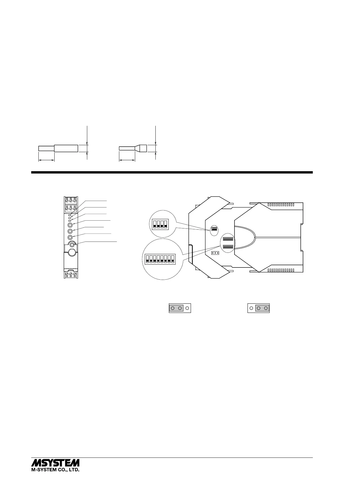
• Expose wire conductors by 8 mm (0.31”).
8 mm 8 mm
4 mm dia.
max.
4 mm dia.
max.
Wire exposure Recommended
ferruled wire
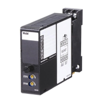
EXTERNAL & INTERNAL VIEWS
87654321
ON
OFF
ON
OFF
4321
Configuration DIP SW
10 11 12
789
456
123
Configurator Jack
DOWN Button
UP Button
MODE Button
LED3 (LD3)
LED2 (LD2)
LED1 (LD1)
FRONT VIEW ■ SIDE VIEW
SW3
SW2
SW1
JP2
2
1
3
JP2
JP2
*
*For Voltage Input (V) range, switch the JP2 jumper to the 2 – 3 position.
Normal Position
(other than DC Voltage [V] range)
DC Voltage [V] Range Position
The DIP switch setting is required to select output types before setting a precise output range using the PC configurator
software.