M3LU
5-2-55, Minamitsumori, Nishinari-ku, Osaka 557-0063 JAPAN
Phone: +81(6)6659-8201 Fax: +81(6)6659-8510 E-mail: info@m-system.co.jp
EM-2652-A Rev.2 P. 7 / 9
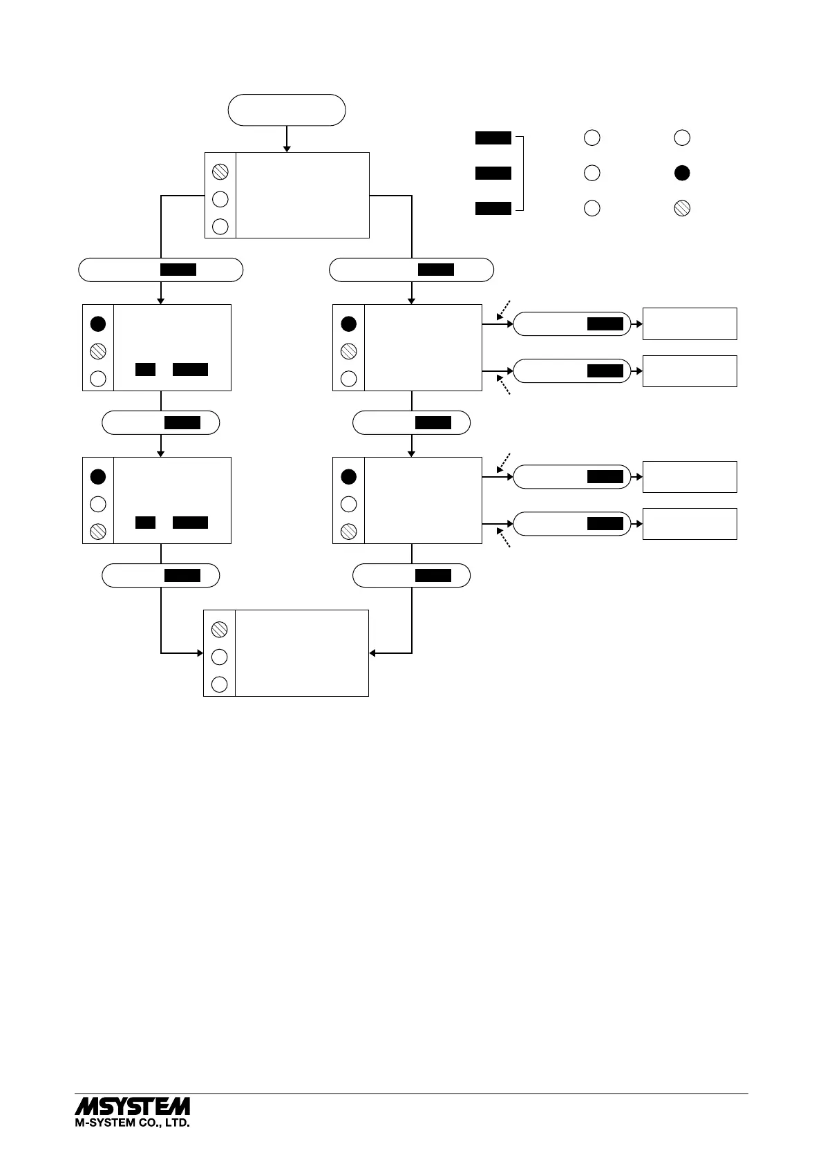
■ CALIBRATION FLOW CHART
POWER ON
Amber LED
Green LED
Control
Buttons
Red LED
OFF
ON
Blink
RUN MODE
LD2
LD3
A
G
RUN MODE
LD2
LD3
G
R
LD1
LD2
LD3
LD1
LD2
LD3
0% INPUT
CONFIGURED
100% INPUT
CONFIGURED
INPUT
RANGING
MODE
LD1
OUTPUT
RANGING
MODE
LD2
LD3
LD1
LD2
LD3
0% OUTPUT
CONFIGURED
100% OUTPUT
CONFIGURED
G
G R
R
R
R
G
R
R
G
Fine Adjustments ? I/O Ranging ?
HOLD DOWN
MODE
1 – 2 s HOLD DOWN
MODE
> 5s
PRESS
MODE
PRESS
MODE
PRESS
MODE
PRESS
MODE
HOLD DOWN
DOWN
HOLD DOWN
UP
DOWN
UP
MODE
HOLD DOWN
DOWN
HOLD DOWN
UP
When you set 0% or 100% input/output ranges,
keep pressing UP or DOWN button until the
LD1 blinks for approx. 2 seconds and turns off,
which indicates the setup is complete.
If the LED does not change, the entered level may
be inappropriate: e.g. out of usable range, burnout
(wire breakdown).
*For the model M3LU-x/A, the green LED is blinking.
For the model M3LU-x/B, the green LED turns on.
FINE ZERO
ADJUSTMENT MODE
UP or DOWN
FINE SPAN
ADJUSTMENT MODE
UP or DOWN
Apply simulated 0% input signal.
Apply simulated 100% input signal.
Adjust simulated input until the output meter
shows desired 0% output.
Adjust simulated input until the output meter
shows desired 100% output.
LD1*
LD1*
■ ZERO & SPAN ADJUSTMENTS
After the transmitter is installed and operational, fine zero and span tuning can be performed as explained below.
Both zero and span are adjustable within ±15%.
1) Run Mode: Confirm that the green LED is blinking
(model M3LU-x/A) or the green LED turns on (model
M3LU-x/B).
2) Fine Zero Adjustment Mode: Hold down MODE button
for 1 or 2 seconds until the LD1 red LED is ON and the
LD2 green LED is blinking.
Use UP (increase) and DOWN (decrease) buttons to
adjust the output to 0%.
3) Fine Span Adjustment Mode: Press MODE button and
confirm that the LD3 green LED instead of LD2 is
blinking.
Use UP (increase) and DOWN (decrease) buttons to
adjust the output to 100%.
4) Run Mode: When fine adjustment is completed, press
MODE button once and confirm that: the LD1 green LED
is blinking in case of M3LU-x/A; and the LD1 green LED
is ON in case of M3LU-x/B.
Note 1: Calibration steps can be skipped when not needed by
repeating pushing MODE buttons.
Note 2: There is no stated order of setting 0% and 100% levels
or no limitation of entering values for multiple times
within one step of Calibration Mode. Signal level is
stored each time the respective UP or DOWN button is
pressed.
 Loading...