P. 1 / 2EM-2468 Rev.7
SIGNAL TRANSMITTER
MODEL
M5VS
INSTRUCTION MANUAL
BEFORE USE ....
Thank you for choosing M-System. Before use, please check
contents of the package you received as outlined below.
If you have any problems or questions with the product,
please contact M-System’s Sales Office or representatives.
■ PACKAGE INCLUDES:
Signal conditioner ......................................................... (1)
Sealing label (option /VN) .................................. (1 sheet)
■ MODEL NO.
Confirm Model No. marking on the product to be exactly
what you ordered.
■ INSTRUCTION MANUAL
This manual describes necessary points of caution when
you use this product, including installation, connection and
basic maintenance procedures.
POINTS OF CAUTION
■ POWER INPUT RATING & OPERATIONAL RANGE
•Locatethepowerinputratingmarkedontheproductand
confirm its operational range as indicated below:
85 – 264V AC rating: 85 – 264V, 47 – 66 Hz, approx. 2 – 3VA
24V DC rating: 24V ±10%, approx. 2W
■ GENERAL PRECAUTIONS
•Beforeyouremovetheunitormountit,turnoffthepower
supply and input signal for safety.
■ ENVIRONMENT
•Indooruse
•Whenheavydustormetalparticlesarepresentintheair,
install the unit inside proper housing with sufficient ven-
tilation.
•Donotinstalltheunitwhereitissubjectedtocontinuous
vibration.Donotsubjecttheunittophysicalimpact.
•Environmentaltemperaturemustbewithin-5to+55°C
(23to131°F)withrelativehumiditywithin0to90%RH
in order to ensure adequate life span and operation.
■ WIRING
•Do not install cables (power supply, input and output)
close to noise sources (relay drive cable, high frequency
line, etc.).
•Do not bind these cables together with those in which
noises are present. Do not install them in the same duct.
•Installlightningsurgeprotectorsforthosewiresconnect-
ed to remote locations. For 24V DC power supply line,
choose a surge protector with its maximum surge voltage
40Vorlessbetweenlines.RecommendedM-Systemmod-
el: MDP-D24.
■ AND ....
•Theunitisdesignedtofunctionassoonaspowerissup-
plied, however, a warm up for 10 minutes is required for
satisfying complete performance described in the data
sheet.
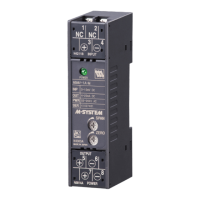
COMPONENT IDENTIFICATION
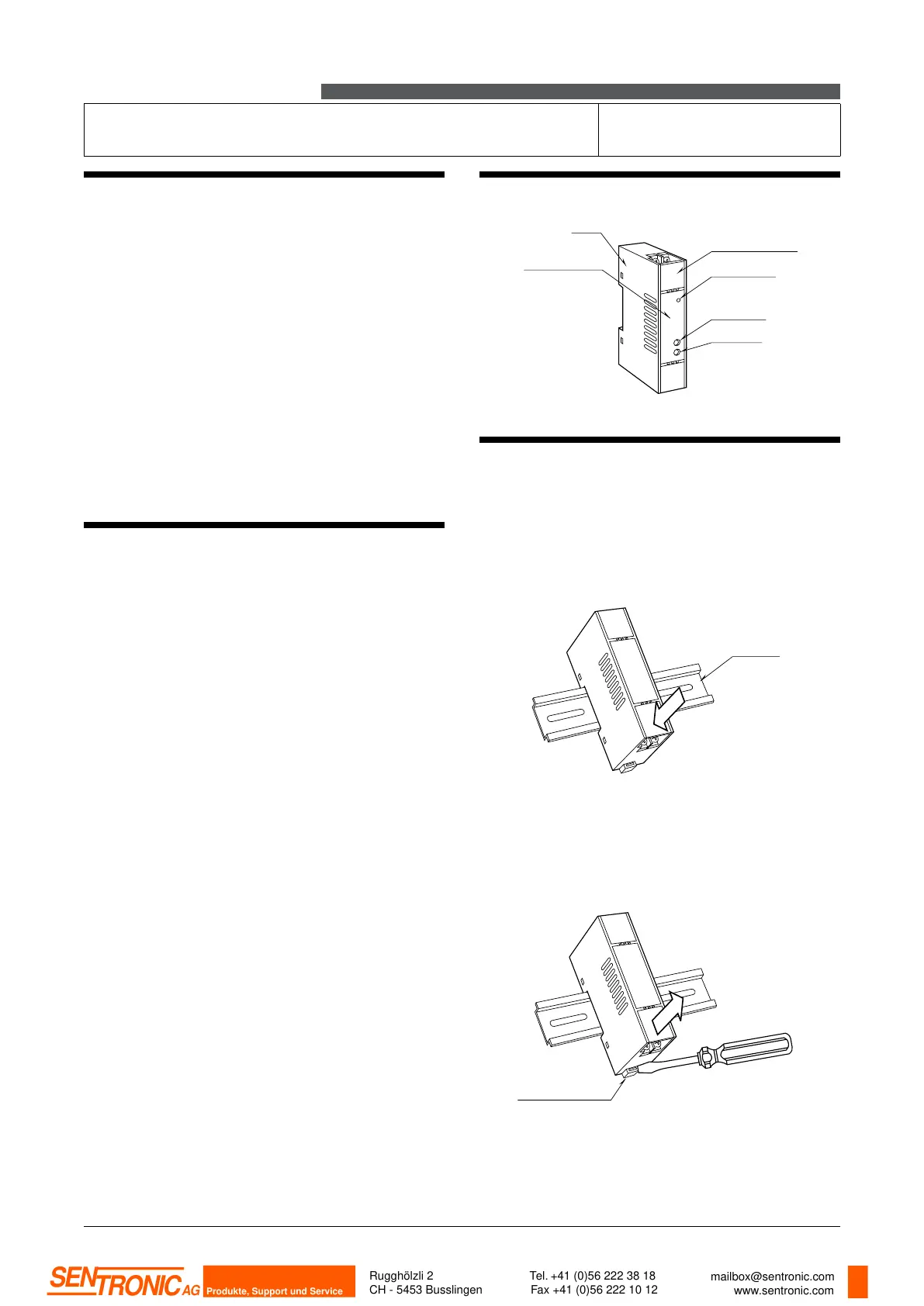
INSTALLATION
Set the unit so that its DIN rail adapter is at the bottom.
■ MOUNTING THE UNIT ON A DIN RAIL
A) Hang the upper hook at the rear side of unit on the DIN
rail.
B) Push in the lower in keeping pressing the unit to the
DIN rail.
■ REMOVING THE UNIT
A) Push down the DIN rail adaptor using a minus screw-
driver.
B) Pull out the lower part of the unit.
C)RemovetheupperpartfromtheDINrail.
Power LED
Terminal Cover
Zero Adj.
Span Adj.
Body
Spec. Marking
A
B
DIN Rail
A
C
B
Spring Loaded
DIN Rail Adaptor
Rugghölzli 2
CH - 5453 Busslingen
Tel. +41 (0)56 222 38 18
Fax +41 (0)56 222 10 12
mailbox@sentronic.com
www.sentronic.com
Produkte, Support und Service
SEN
TRONIC
AG
 Loading...