ME401-2
M-Tec ME401-2, Technical Manual v.1.3a, September 2012 Page 13
NOTE: Enabling the filtering function will disable the use of the alarm function on digital
input 4 as listed in the standard installation proposal above.
NOTE: It is recommended always to connect digital input 2 to the ignition signal of the
machine as this is necessary for km recording.
NOTE: For the “Send SMS” it is of no importance if small or capital letters are used in
the command string, or a mixture hereof.
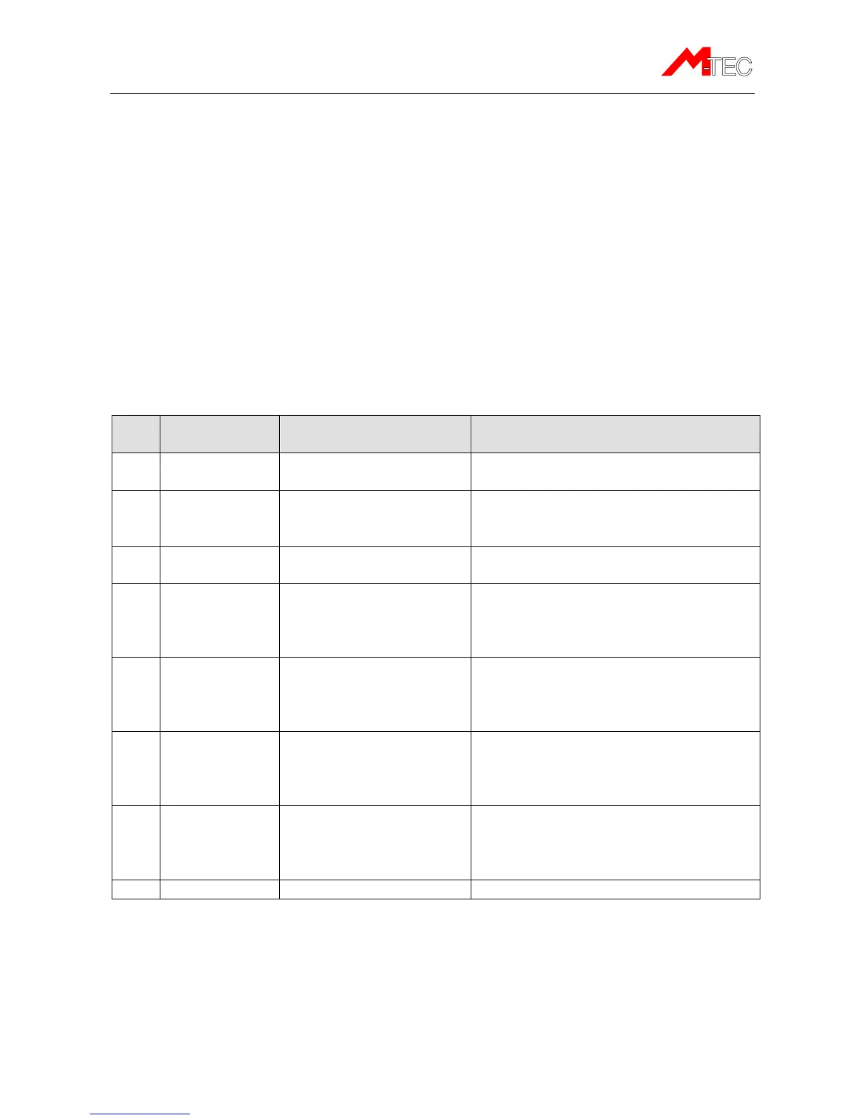
Installation of the ME401-2 in vehicles
The standard installation for vehicles, where the unit should register operating hours and
record km, the following connections are used:
1 Red Power Connect to a fixed DC supply through
a 1 amp. fuse.
2 White Digital input 1 Connect to the operating hours
counter.
(Min. 8V DC voltage at the input)
3 Brown Digital input 2 Connect to the ignition signal
(Min. 8V DC voltage at the input)
4 Grey Digital input 3 Can be connected to an external
sensor or it can be connected to a
ID06 Card reader.
(Min. 8V DC voltage at input)
5 Pink Digital input 4 Can be connected to an external
sensor for detecting a critical running
mode or an alarm
(Min. 8V DC voltage at input)
6 Green 1-wire input Can be used to connect one or two
temperature sensors or a Dallas Key
reader to control an immobilizer relay
connected to Digital output 1
7 Yellow Digital output 1 Can be used to control external
equipment through a relay (see
example in “Installation of the digital
output”. Max. Load 200 mA)
8 Blue Ground
NOTE: It is recommended always to connect digital input 2 to the ignition signal of the
vehicle as this is necessary for km recording.