19
RedBlack
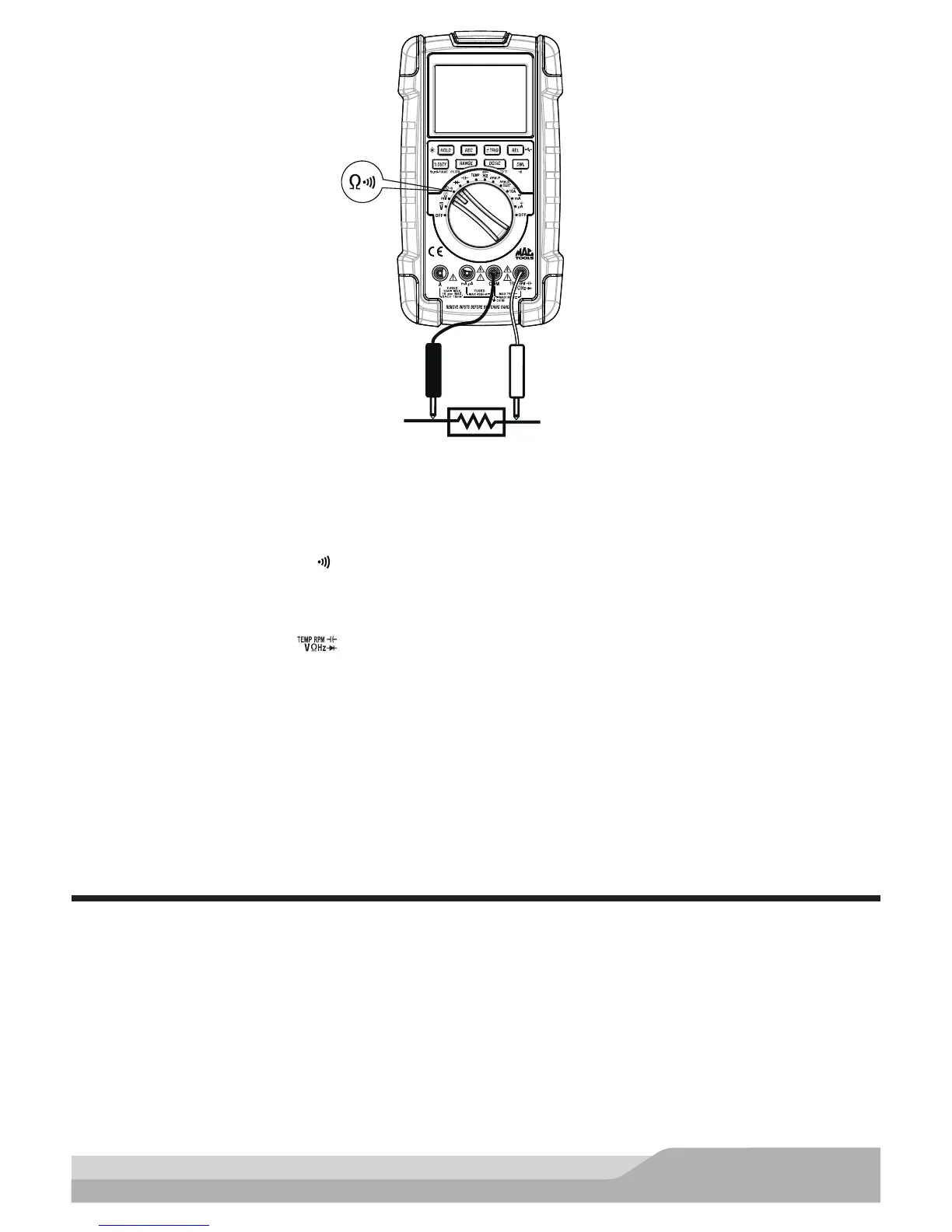
Parallel Connection
Meter setup to measure resistance:
• Set the rotary switch to the Ω setting. The meter defaults to resistance measurement function.
• If a more accurate measurement is desired, select the proper resistance range by pressing the “RANGE”
button.
• Insert the black lead in the “COM” jack.
• Insert the red lead in the “ ” jack.
Connect:
• Test probes across the resistor or circuit to be tested.
Accuracy:
Rapidly changing display readings (noise) can sometimes be eliminated if you change to a higher range. You
can also smooth out noise somewhat by using the averaging (AVG) feature provided by the Recording function.
Continuity Test
A continuity test is a static test (circuit power off) that allows you to quickly and easily distinguish between
an open and a closed circuit. When the meter detects a closed circuit or short, it beeps so you do not have to
look at the meter during the test. This can be a valuable troubleshooting aid when determining good or blown
fuses and fusible links, open or shorted conductors and wires, operations of switches, etc. It is also helpful for
troubleshooting in out-of-the-way locations where it is difcult to watch the readout at all times.
NOTE: Turn off power to the circuit to be tested.
A beeper tone does not necessarily means zero resistance.