64
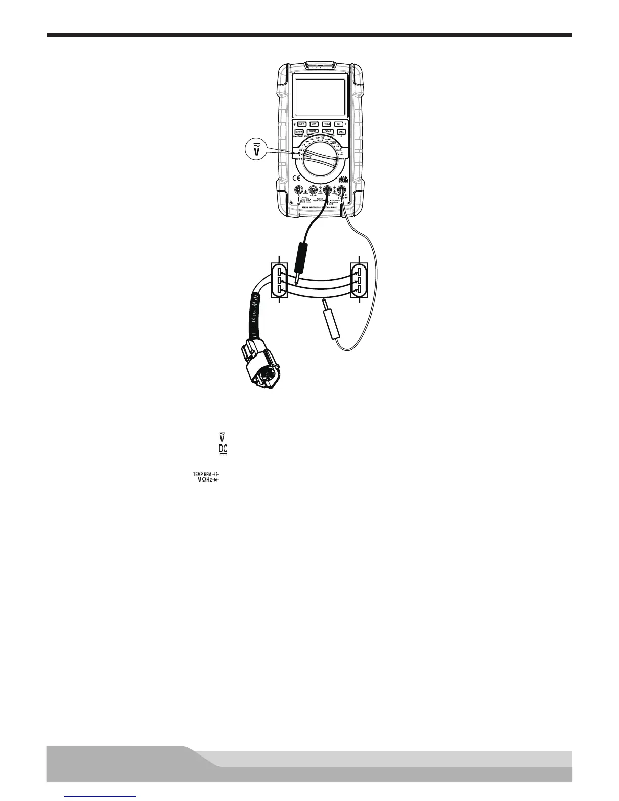
Potentiometer Voltage Change Test
Red
Black
Jumper
Wires
TPS
Connector
5V Supply
Ground
Signal
Meter setup to check voltage change:
• Set the rotary switch to voltage ( ) setting.
• Press the “DC/AC” button until “ ” appears on the display.
• Insert the black lead in the “COM” jack.
• Insert the red lead in the “ ” jack.
• Press the “REC” button (selects the MAX.MIN.AVG function).
Disconnect the sensor connector and connect jumper wires between the connector and the sensor.
Connect:
• Black test probe to the ground circuit.
• Red test probe to the signal line.
Turn the ignition key on; do not start the engine.
Rotate the TPS by moving the throttle and watch the bargraph move. The volatge drop should change as the
position of the signal arm on the TPS moves (signal sweep).
The bargraph should increase smoothly without jumping if the TPS is good.
Refer to the manufacturer’s specications. If the voltage change is not within the specications, check for
sources of excess resistance before replacing potentiometer: poor connectors, connections, or breaks in the
wiring.