65
NOTE: Do not insert the test probe tips into the TPS as they may damage the smaller type plug on the TPS
connector.
Oxygen (O
2
) Sensor Test
The Oxygen (Lambda) Sensor samples the amount of oxygen (O
2
) in the exhaust stream. The O
2
sensor produces
an output voltage that is a direct ratio to the oxygen level in the exhaust stream. The vehicle computer uses this
signal to change the air/fuel mixture ratio.
This test checks the signal output voltage levels of the O
2
sensor.
O
2
Black
Red
Sensor
Signal Output
Voltage Wire
Exhaust
Manifold
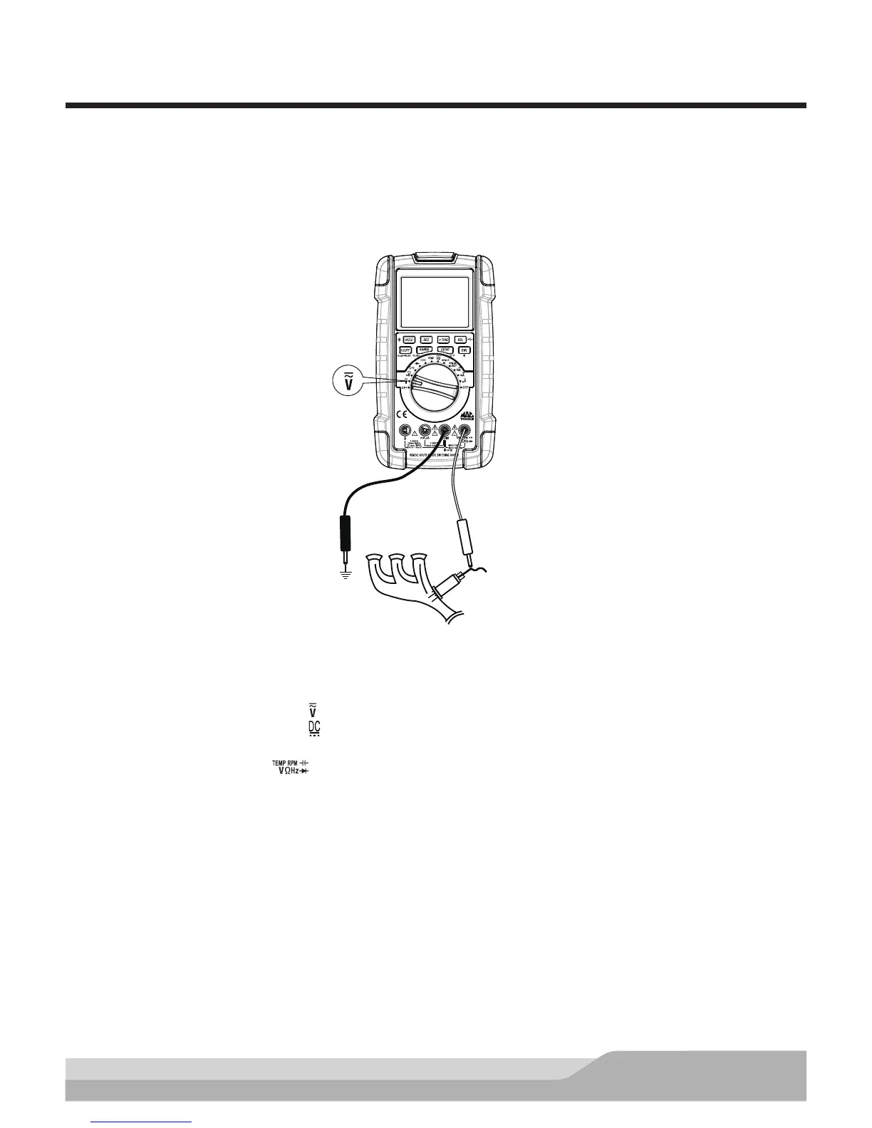
Meter setup to measure signal output voltage of the oxygen sensor:
• Set the rotary switch to voltage ( ) setting.
• Press the “DC/AC” button until “ ” appears on the display.
• Insert the black lead in the “COM” jack.
• Insert the red lead in the “ ” jack.
• Press the “REC” button (selects the MAX.MIN.AVG function).
Connect:
• Black test probe to a good quality ground.
• Red test probe to the signal output voltage wire.
NOTE: Be careful not to burn yourself on the hot exhaust manifold.
Run the engine at a fast idle (2,000 RPMs) for a few minutes. The O
2
voltage readings should sweep between
100mV (lean) and 900mV (rich).
Once the O
2
sensor reaches operating temperature, the DC voltage reading should begin to sweep. Under
varying operating conditions, the O
2
voltage will rise and fall, but usually averages around 0.45V dc.