ENGLISH
8
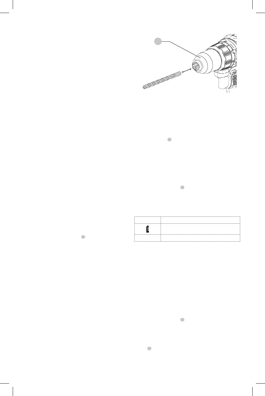
Installing a Bit or Accessory into a
Keyless Chuck (Fig. C)
WARNING: Do not attempt to tighten drill bits (or
any other accessory) by gripping the front part of the
chuck and turning the tool on. Damage to the chuck
and personal injury may result. Always lock off trigger
switch and disconnect tool from power source when
changingacces sories.
WARNING: Always ensure the bit is secure before
starting the tool. A loose bit may eject from tool
causing possible personalinjury.
Your tool features a keyless chuck
8
with one rotating
sleeve for one-handed operation of the chuck. To insert a
drill bit or other accessory, follow thesesteps.
1. Turn tool off and remove battery pack.
2. Grasp the black sleeve of the chuck with one hand
and use the other hand to secure the tool. Rotate the
sleeve counterclockwise far enough to accept the
desiredaccessory.
3. Insert the accessory about 3/4" (19 mm) into the chuck
and tighten securely by rotating the chuck sleeve
clockwise with one hand while holding the tool with the
other. Your tool is equipped with an automatic spindle
lock mechanism. This allows you to open and close the
chuck with onehand.
Be sure to tighten chuck with one hand on the chuck sleeve
and one hand holding the tool for maximumtightness.
To release the accessory, repeat steps 1 and 2above.
ASSEMBLY AND ADJUSTMENTS
WARNING: To reduce the risk of serious personal
injury, turn unit off and remove the battery pack
before making any adjustments or removing/
installing attachments or accessories. An
accidental start-up can causeinjury.
Intended Use
This tool is a professional power tool designed for drilling
andscrewdriving.
DO NOT use under wet conditions or in presence of
flammable liquids orgases.
DO NOT let children come into contact with the tool.
Supervision is required when inexperienced operators use
thistool.
Speed Selection (Fig. A)
The tool features two speed settings for greaterversatility.
NOTE: Do not change speeds when the tool is running.
Always allow the tool to come to a complete stop before
changingspeed.
1. To select speed 1 (higher torque setting), slide the
speed selector
6
forward (towards from the chuck).
2. To select speed 2 (lower torque setting), slide the speed
selector back (away from the chuck).
If the tool does not change speeds, confirm that the speed
selection switch is completely engaged in the forward or
back position.
Mode Selection (Fig. A)
The mode selection collar
5
can be used to select
the correct operating mode depending upon the
plannedapplication.
To select, rotate the collar until the desired symbol aligns
with thearrow.
Symbol Mode
Drilling
1–15 Screwdriving (higher number = greater torque)
OPERATION
WARNING: To reduce the risk of serious personal
injury, turn unit off and remove the battery pack
before making any adjustments or removing/
installing attachments or accessories. An
accidental start-up can causeinjury.
Installing and Removing the Battery Pack
(Fig. D)
NOTE: For best results, make sure your battery pack is
fullycharged.
To install the battery pack
1
into the tool handle, align the
battery pack with the rails inside the tool’s handle and slide
it into the handle until the battery pack is firmly seated in
the tool and ensure that it does notdisengage.
To remove the battery pack from the tool, press the release
button
2
and firmly pull the battery pack out of the tool
handle. Insert it into the charger as described in the charger
section of thismanual.
the location of the mounting screws on the wall. Mount
the charger securely using drywall screws (purchased
separately) at least 1" (25.4 mm) long, with a screw head
diameter of 0.28–0.35" (7–9mm), screwed into wood to an
optimal depth leaving approximately 7/32" (5.5 mm) of the
screw exposed. Align the slots on the back of the charger
with the exposed screws and fully engage them in theslots.
Fig.C
8