38
MAC 6000 Hydronic Heater
Trailer Axle Manual
2106 East Indiana Ave., Bismarck, ND 58504 U.S.A. • www.macheaters.com • +1-800-272-4604
15
Rev: 07.25.2013
TORQUE REQUIREMENTS
It is extremely important to apply and maintain proper wheel mounting torque
on your trailer axle. Torque wrenches assure the proper amount of torque is being
applied to a fastener. Use no other method to torque fasteners.
Proper and accurate torque must be maintained to prevent wheels from loosening,
studs from cracking and/or breaking or other possible hazardous breakage resulting
in serious injury or death.
Be sure to use only the fasteners matched to the cone angle of your wheel (usually
60°or 90°.) The proper procedure for attaching your wheels is as follows:
1. Start all bolts or nuts by hand to prevent cross threading.
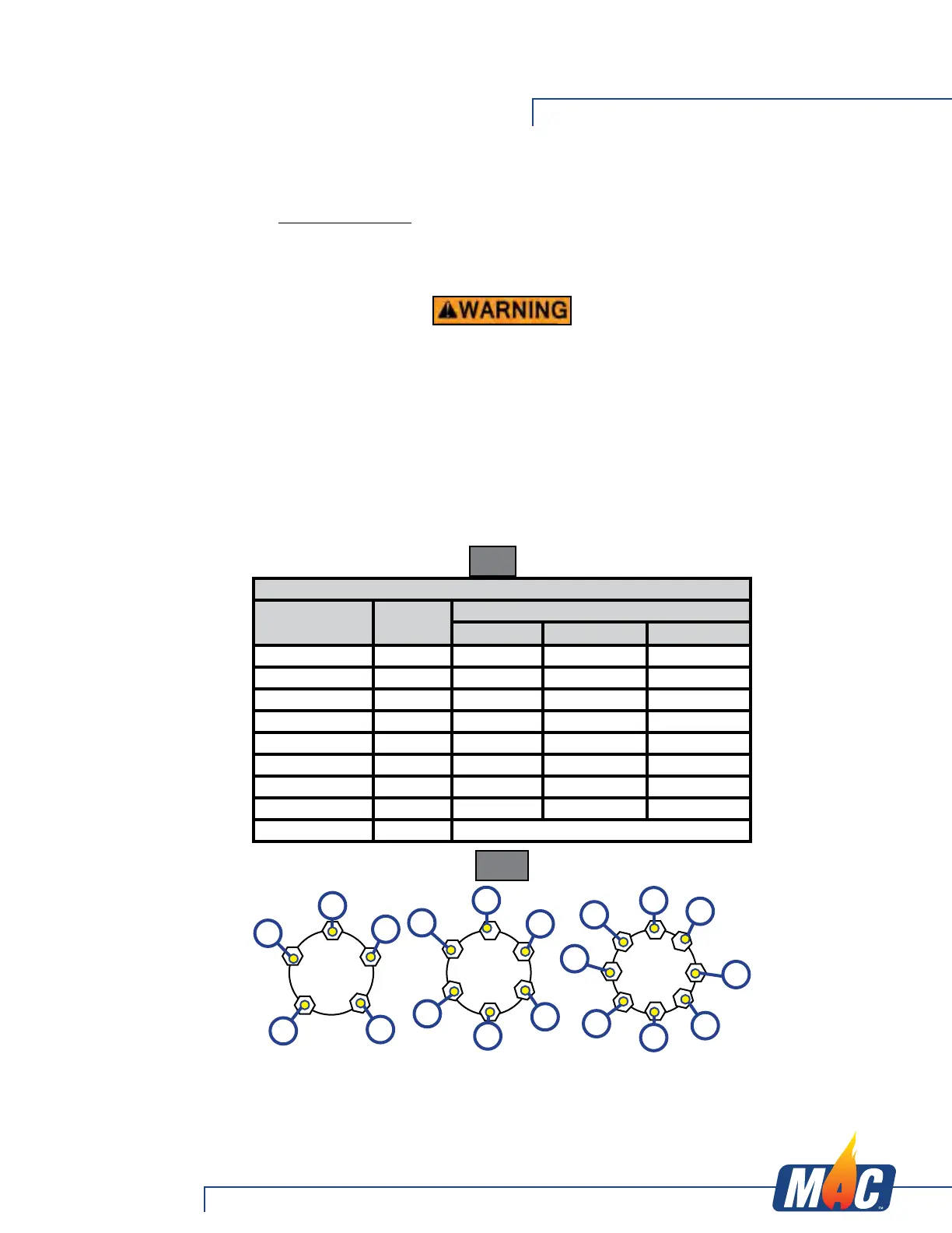
2. Tighten bolts or nuts in the following sequence.
3. Tightening fasteners should be done in stages. Follow the recommended
sequence, tighten fasteners per wheel torque requirements diagram (Fig. 9).
4. Wheel nuts/bolts should be torqued before first road use and after each wheel
removal. Check and re-torque after the 10 and 25 miles and again at 50 miles. A
periodic check during regular service is recommended.
Wheel Torque Requirement Chart
Wheel Size
Stud
Size
Torque Sequence
!st Stage 2nd Stage 3rd Stage
14" 1/2" 20-25 ft-lbs 50-60 ft-lbs 90-120 ft-lbs
15" 1/2" 20-25 ft-lbs 50-60 ft-lbs 90-120 ft-lbs
16" 1/2" 20-25 ft-lbs 50-60 ft-lbs 90-120 ft-lbs
16.5" x 6.75" 1/2" 20-25 ft-lbs 50-60 ft-lbs 90-120 ft-lbs
16" 9/16" 20-25 ft-lbs 60-70 ft-lbs 120-130 ft-lbs
16.5" x 6.75" 9/16" 20-25 ft-lbs 60-70 ft-lbs 120-130 ft-lbs
17.5" Long Nut 5/8" 50-60 ft-lbs 100-120 ft-lbs 190-210 ft-lbs
17.5" Flange Nut 5/8" 50-60 ft-lbs 150-200 ft-lbs 275-325 ft-lbs
14.5" Demount 5/8" Tighten sequentially to 85-95 ft-lbs
Fig. 9
1
1
2
5
4
3
1
3
2
4
5
6
1
3
2
4
5
6
8
7
Fig. 10
Axles and Suspension Systems