EasyManua.ls Logo

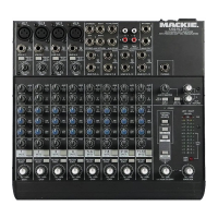
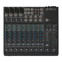
Mackie 1202 VLZ User Manual

Mackie 1202 VLZ
50 pages
To Next Page IconTo Next Page
Page #1 background imageLoading...
Page #1 background image
MICROSERIES1202-VLZ
MIC
/
LINE MIXER
OWNERS MANUAL
U
OO
+15
U
OO
+15
U
+15
-15
U
+12-12
U
+15-15
LR
U
+20dB
OO
U
+20dB
OO
U
+20dB
OO
U
+20dB
OO
U
+20dB
OO
U
+20dB
OO
U
+20dB
OO
U
OO
+10
U
OO
+20
U
OO
+20
U
+20dB
OO
U
MAX
OO
U
+10dB
OO
U
OO
+15
U
OO
+15
U
+15-15
U
+12-12
U
+15-15
LR
U
OO
+15
U
OO
+15
U
+15-15
U
+12-12
U
+15
-15
LR
U
OO
+15
U
OO
+15
U
+15-15
U
+12-12
U
+15-15
LR
U
OO
+15
U
OO
+15
U
+15-15
U
+12
-12
U
+15-15
LR
U
OO
+15
U
OO
+15
U
+15-15
U
+12-12
U
+15
-15
LR
U
OO
+15
U
OO
+15
U
+15-15
U
+12
-12
U
+15-15
LR
U
OO
+15
U
OO
+15
U
+15-15
U
+12-12
U
+15
-15
LR
RUDE
SOLO
LIGHT
U
BAL
M
I
C
G
A
I
N
10
U
60
+10dB
-40dB
-
1
0
M
I
C
G
A
I
N
10
U
60
+10dB
-40dB
-
1
0
M
I
C
G
A
I
N
10
U
60
+10dB
-40dB
-
1
0
M
I
C
G
A
I
N
10
U
60
+10dB - 40dB
-
1
0
11 12
MUTE
9 10
MUTE
7 8
MUTE
5 6
MUTE
4
MUTE
3
MUTE
2
MUTE
1
MUTE
MICRO SERIES 1202-VLZ
12-CHANNEL MIC/LINE MIXER
+28
CLIP
0dB=0dBu
+10
LEFT
RIGHT
+7
+4
+2
0
-2
-4
-7
-10
-20
-30
HI
12kHz
MID
2.5kHz
LOW
80Hz
EQ
AUX
PAN
PRE FADER
SOLO
PRE FADER
SOLO
PRE FADER
SOLO
PRE FADER
SOLO
PRE FADER
SOLO
PRE FADER
SOLO
PRE FADER
SOLO
PRE FADER
SOLO
1
2
POWER
AUX 1 MASTER
AUX
RETURN
1
2
LINE IN 1
LINE IN 2
LINE IN 3
LINE IN 4
L
MONO
L
MONO
L
MONO
L
MONO
PHONES
LINE IN 5-6
R
R
R
R
AUX SEND
TAPE
INPUT
TAPE
OUTPUT
L
R
1
2
1
2
RIGHT
L
R
RIGHT
TRIM
MIC
1
MIC
2
MIC
3
MIC
4
LEFT
LEFT/
MONO
STEREO AUX RETURNS
MAIN OUTS
BAL/UNBAL
LINE IN 7-8
LINE IN 9-10
LINE IN 11-12
GAIN
GAIN
GAIN
GAIN
GAIN
GAIN
GAIN
GAIN
MAIN MIX
/ PHONES
LEVEL SET
ALT 3
-
4
ASSIGN
TO MAIN MIX
SOURCE
TAPE
MAIN
MIX
LOW CUT
75 Hz
18dB/OCT
TRIM
LOW CUT
75 Hz
18dB/OCT
TRIM
LOW CUT
75 Hz
18dB/OCT
TRIM
LOW CUT
75 Hz
18dB/OCT
ALT 3
-
4
ALT 3
-
4
ALT 3
-
4
ALT 3
-
4
ALT 3
-
4
ALT 3
-
4
ALT 3
-
4
ALT 3
-
4
BAL
OR
UNBAL
BAL
OR
UNBAL
BAL
OR
UNBAL
BAL
OR
UNBAL
BAL
OR
UNBAL
BAL
OR
UNBAL
BAL
OR
UNBAL
BAL
OR
UNBAL
ALL BAL/UNBAL
EFX TO
MONITOR
MON/
EFX
1
MON/
EFX
1
MON/
EFX
1
MON/
EFX
1
MON/
EFX
1
MON/
EFX
1
MON/
EFX
1
MON/
EFX
EFX
HI
12kHz
MID
2.5kHz
LOW
80Hz
EQ
AUX
PAN
2
EFX
HI
12kHz
MID
2.5kHz
LOW
80Hz
EQ
AUX
PAN
2
EFX
HI
12kHz
MID
2.5kHz
LOW
80Hz
EQ
AUX
PAN
2
EFX
HI
12kHz
MID
2.5kHz
LOW
80Hz
EQ
AUX
PAN
2
EFX
HI
12kHz
MID
2.5kHz
LOW
80Hz
EQ
AUX
PAN
2
EFX
HI
12kHz
MID
2.5kHz
LOW
80Hz
EQ
AUX
PAN
2
EFX
HI
12kHz
MID
2.5kHz
LOW
80Hz
EQ
AUX
PAN
2
EFX
NORMALLED
MON/PRE
POST
AUX 1
SELECT
CONTROL
ROOM
TM
POWER
CONCEIVED, DESIGNED, AND MANUFACTURED BY MACKIE DESIGNS INC.
ON
PHANTOM
ON
LEFT
MAIN
OUTPUT
LEVEL
RIGHT
4
3
R
L
2
1
CHANNEL INSERTS
LOW NOISE HIGH HEADROOM
12-CHANNEL MIC/LINE MIXER
MADE IN USA
WOODINVILLE WASHINGTON
BAL/UNBAL BAL/UNBAL
MICRO SERIES
1202-VLZ
120 VAC 50/60 Hz 20W
315mA/250V SLO-BLO
PRE-FADER / PRE EQ TIP SEND / RING RETURN
ALT
OUTPUT
R
L
CONTROL
ROOM
TO REDUCE THE RISK OF
FIRE REPLACE WITH SAME
TYPE FUSE AND RATING
CAUTION:
MIC
+4
SERIAL NUMBER
MANUFACTURING DATE
RISK OF ELECTRIC SHOCK
DO NOT OPEN
REPLACE WITH THE SAME TYPE FUSE AND RATING.
DISCONNECT SUPPLY CORD BEFORE CHANGING FUSE
UTILISE UN FUSIBLE DE RECHANGE DE MÊME TYPE.
DEBRANCHER AVANT DE REMPLACER LE FUSIBLE
WARNING:
TO REDUCE THE RISK OF FIRE OR ELECTRIC SHOCK, DO NOT
EXPOSE THIS EQUIPMENT TO RAIN OR MOISTURE. DO NOT REMOVE COVER.
NO USER SERVICEABLE PARTS INSIDE. REFER SERVICING TO QUALIFIED PERSONNEL.
CAUTION
AVIS :
RISCQUE DE CHOC ÉLECTRIQUE — NE PAS OUVRIR
(
)

Other manuals for Mackie 1202 VLZ

Question and Answer IconNeed help?

Do you have a question about the Mackie 1202 VLZ and is the answer not in the manual?

Mackie 1202 VLZ Specifications

General IconGeneral
Channels12
Mic Preamps4
EQ Bands3-band
Aux Sends2
Phantom PowerYes
TypeAnalog
Returns2 stereo
Headphone Output1
Weight7 lbs
Tape Inputs1 (stereo)
Tape Outputs1 (stereo)

Summary

LEVEL-SETTING PROCEDURE

INSTANT MIXING GUIDE

Quick guide to setting up and using the mixer for immediate playback.

INTRODUCTION TO THE MANUAL

HOW TO USE THIS MANUAL

Guidance on how to navigate and understand the manual's layout and features.

HOOKUP DIAGRAMS OVERVIEW

MORE HOOKUP DIAGRAMS

Provides additional connection examples and diagrams for various setups.

PATCHBAY DESCRIPTION

MIC INPUTS

Details on balanced XLR mic inputs for channels 1-4.

PHANTOM POWER

Explanation of phantom power, its function, and important usage warnings.

LINE INPUTS (Channels 1-4)

Description of line-level inputs for channels 1-4, their connectivity, and level adjustment.

LOW CUT FILTER

Explanation of the low-cut filter function, its frequency, and recommended usage.

TRIM CONTROL

Details on the TRIM control for adjusting input sensitivity and gain on channels 1-4.

STEREO LINE INPUTS (Channels 5-12)

Information on stereo and mono line inputs for channels 5-12, including jack normalling.

EFFECTS PROCESSING

Explains the terms 'serial' and 'parallel' as they relate to effects processing.

CHANNEL INSERT JACKS

Details on using channel insert jacks for serial effects or as direct outputs.

AUX RETURNS

Description of auxiliary return inputs for parallel effects and their usage with stereo or mono devices.

TAPE INPUT

Information on the RCA tape input jacks for connecting tape decks or portable players.

XLR MAIN OUTPUTS

Details on the balanced XLR main outputs, their level capabilities, and wiring.

XLR OUTPUT LEVEL SWITCH

Explanation of the 30dB pad switch for the XLR main outputs.

1/4" MAIN OUTPUTS AND TAPE OUTPUT

Description of 1/4" balanced outputs and unbalanced RCA tape outputs for recording.

PHONES, ALT 3/4, CONTROL ROOM OUTPUTS

Details on headphone, ALT 3/4, and control room outputs and their connectivity.

AUX SEND 1 & 2

Information on the 1/4" balanced auxiliary send outputs for effects or monitor mixes.

CHANNEL STRIP DESCRIPTION

UNITY GAIN AND GAIN CONTROLS

Explanation of unity gain, the GAIN knob, and their function in setting channel levels.

SOLO AND MUTE/ALT 3-4 FUNCTIONS

Functionality of the SOLO and MUTE/ALT 3-4 switches for monitoring and routing.

PAN AND 3-BAND EQ CONTROLS

Details on PAN control for stereo imaging and the 3-band EQ for tonal shaping.

EQ CONTROL DETAILS

Detailed explanation of the LOW, MID, and HI EQ controls and their frequency responses.

AUX SEND FUNCTIONALITY

Explanation of AUX SENDs for effects, stage monitoring, and pre/post-fader modes.

OUTPUT SECTION DESCRIPTION

MAIN MIX AND VLZ ARCHITECTURE

Description of the MAIN MIX control and the mixer's Very Low Impedance (VLZ) design.

SOURCE MATRIX SELECTION

Details on choosing monitoring sources via the SOURCE matrix switches.

CONTROL ROOM/PHONES LEVEL AND PFL

Functionality of monitoring level controls and Pre-Fader Solo for channel inspection.

SOLO LIGHT, ASSIGN TO MAIN MIX, METERS

Explanation of SOLO light, ASSIGN TO MAIN MIX switch, and the metering system.

AUX TALK, AUX 1 SELECT, AUX 1 MASTER

Details on AUX TALK, AUX 1 SELECT switch, and the AUX 1 MASTER control.

ADDITIONAL FEATURES

AUX RETURNS AND EFX TO MONITOR

Control of AUX RETURN levels and the EFX TO MONITOR switch function.

JACK NORMALLING

Explanation of jack normalling features and their use with EFX TO MONITOR switch.

MODIFICATIONS

PRE-FADER MOD (AUX TO MONITOR)

Instructions for modifying AUX SEND 2 to be pre-fader and pre-mute.

PRE-MUTE MOD

Instructions for modifying AUX SEND 1 and 2 to ignore MUTE/ALT 3-4 switch positions.

MAIN MIX SOURCE MOD

Modification to tap the MAIN MIX signal before the level control (pre).

BLOCK DIAGRAM

GAIN STRUCTURE DIAGRAM

SPECIFICATIONS

SERVICE AND TROUBLESHOOTING

TROUBLESHOOTING GUIDE

Steps to diagnose and resolve common channel, output, and noise issues.

REPAIR PROCEDURES

Instructions for sending the mixer for service, including RA number and shipping details.

APPENDIX A: GLOSSARY

APPENDIX B: CONNECTIONS

XLR, TRS, AND TS CONNECTOR TYPES

Details on XLR, TRS, and TS connector types, their pin assignments, and usage.

RCA CONNECTORS AND SPECIAL MACKIE WIRING

Information on RCA connectors and Mackie's specific wiring for inserts and unbalanced connections.

STEREO INPUTS/RETURNS AND MULTS

Explanation of flexible stereo usage and using mults/Y-connectors for signal routing.

APPENDIX C: BALANCED LINES, PHANTOM POWERING, GROUNDING AND OTHER ARCANE MYSTERIES

BALANCED LINES AND PHANTOM POWERING

Benefits of balanced lines and detailed explanation of phantom power for microphones.

PHANTOM POWER DO & DON'T CHART

Chart outlining proper and improper usage of phantom power with various devices.

GROUNDING BEST PRACTICES

Guidelines for proper grounding to ensure safety and minimize noise issues.

FREE T-SHIRT OFFER

Information on how to obtain a free Mackie T-shirt by submitting project details.

Related product manuals