The above-said operations must
be carried out only by qualifi e d
technicians.
9
19
19
SERVICING
In all cases, before performing any internal
checks make sure that:
1. the power supply to the device is
disconnected
2. there is no pressurised gas inside the device
• DN 15 ÷ DN 25: (see fi g . 1 a n d 2 ) u n s c r e w
the coil fi x i n g s c r e w s ( 12) (or the slow
opening kit (17)) and remove the coil
(11). Unscrew the cover fi x i n g s c r e w s
(9) and disassemble it from body valve
(4). Check the obturator (5), clean or if is
necessary sobstitute the rubber made seal
component. Clean the fi l t e r ( 8) blowing it
without taking it off the body valve (4).
Then assemble doing backward the same
operation of dismantling.
• DN 32 ÷ DN 150: (see fi g . 3 , 4 , 5 , 6 ) u n s c r e w
the nut (12) (or the slow opening kit (17))
and remove the coil (11). Unscrew the
fi x i n g s c r e w s ( 9) and, with care, take the
cover (10) off the body (4) of the valve,
then control the obturator (5) and if it is
necessary change the rubber made seal
component (6). Then clean or blow the fi l t e r
(8) or change it if necessary; then assemble
doing backward the same operation.
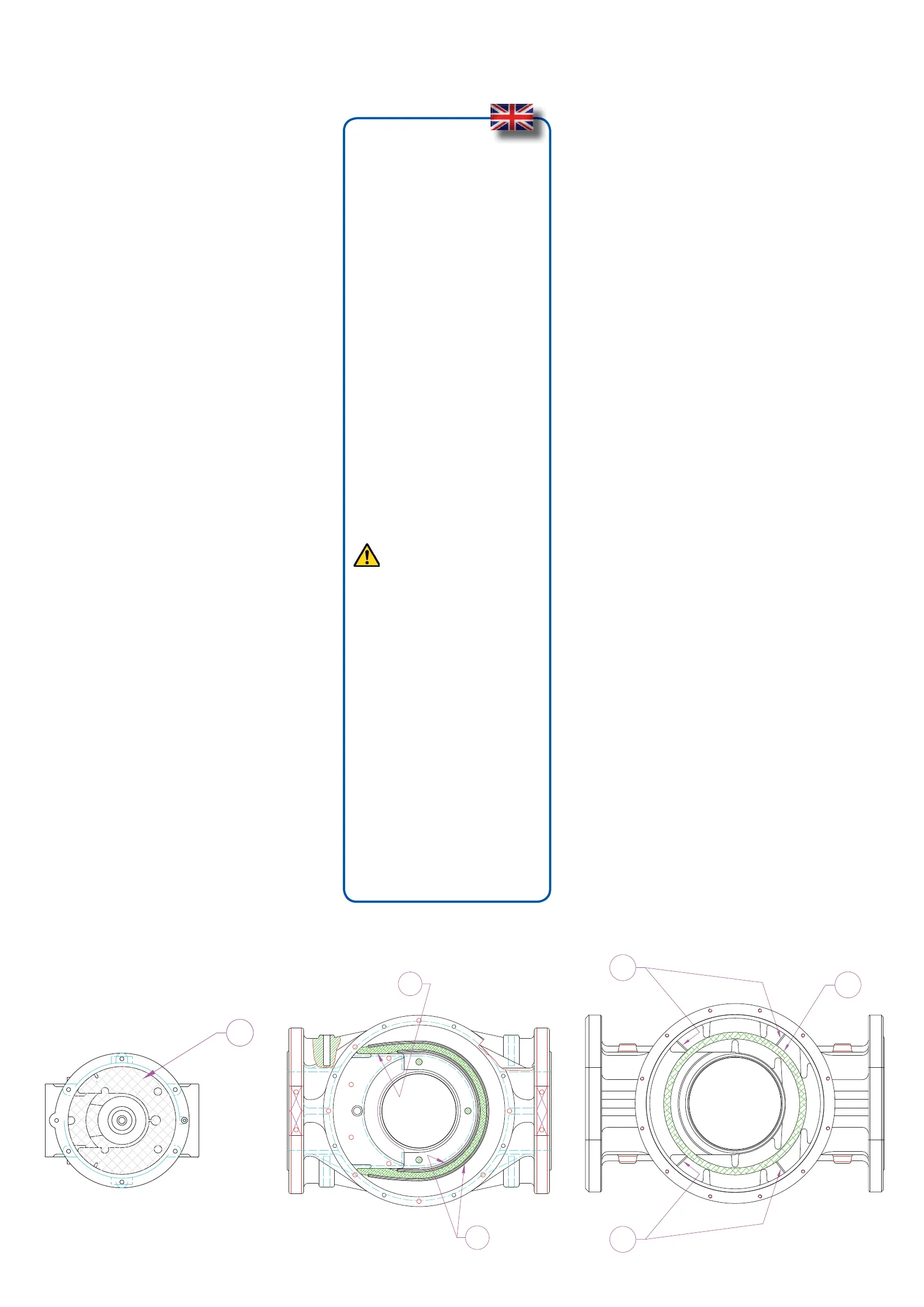
VIEW: BODY OF THE VALVE WITHOUT
COVER
TO INSERT THE NET
DN 32 ÷ DN 50:
Position it as in the fi g u r e t a k i n g c a r e t o r e s p e c t
the guides in the internal circumference of
the body valve and fi x i t b y t h e t h r e e s p e c i a l
screws (M3x10).
TO INSERT THE FILTERING ORGAN:
DN 65 ÷ DN 100:
Position it as in the fi g u r e t a k i n g c a r e t o p u t
it inside the guides (18).
DN 125 - DN 150:
Put it as in fi g u r e , s o t h a t t h e s p e c i a l fi n s ( 19)
are leant against the body. So reassemble
the cover paying attention that the O-Ring
is into the right hole.
18
8
8
fi g . 5