This document is an operation manual for the MAEDA CRAWLER CRANE LC785M-6B BLADE, specifically for models with serial number 31460 and up. It provides detailed information on the blade's operation, safety precautions, maintenance, and specifications.
Function Description
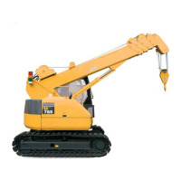
The LC785M-6B BLADE is a crawler crane equipped with a blade, primarily used for ground leveling operations. The blade is controlled by a dedicated lever inside the cabin. The manual emphasizes that the blade should not be used as an outrigger, as this could damage the crane or cause it to tip over.
Important Technical Specifications
Machine Mass and Dimensions (LC785M-6B):
- Machine mass: 10,250 kg
- Overall length x width x height: 5,005 mm x 2,350 mm x 2,685 mm
- Distance between idler and sprocket: 2,235 mm
- Track gauge: 1,870 mm
- Track width: 450 mm
- Lowest height from ground: 360 mm
Blade System:
- Method: Direct push with hydraulic cylinder
- Blade maximum rising stroke: 380 mm
- Blade maximum lowering stroke: 245 mm
Hydraulic System:
- Hydraulic pump: Variable piston pump + dual gear pump (Winch / Travel-right / Telescoping & Winch / Derricking / Travel-left, Slewing & Control valves)
- Relief set pressure:
- 20.6 MPa (210 kgf/cm²) for telescope, derrick
- 24.6 MPa (250 kgf/cm²) for winch, travel
- 19.2 MPa (195 kgf/cm²) for swing
- 3.2 MPa (32 kgf/cm²) for control
- Hydraulic oil tank capacity: 126 liters
Hoisting Wire Ropes (for machine hoisting):
- For boom lowered (4-part hanging):
- Four hoisting wire ropes of the same standard
- Breaking force: 18.7 ton or more
- Diameter: 18 mm x 2.0 m or more
- Four shackles of the same standard
- Working load: 3.0 ton or more per single line
- For boom raised (2-part hanging):
- Two hoisting wire ropes of the same standard
- Breaking force: 36 ton or more
- Diameter: 25 mm x 8.6 m or more
- Two shackles of the same standard
- Working load: 7.0 ton or more per single line
Usage Features
Blade Operation:
The blade is operated using the blade control lever (17) located on the right side of the operator's seat.
- Lower: Push the lever forward.
- Raise: Draw the lever backward.
- Neutral: The blade stops tilting and is held in position.
Safety Precautions for Blade Operation:
- Hoisting Operations: Always clear the blade from the ground during hoisting. Avoid ground leveling operations simultaneously with hoisting.
- Ground Leveling Posture: For ground leveling, the blade must be kept ahead, the boom retracted to minimum, the hook stowed, and the boom lowered to a range between "full lowered to 35 degrees." Raising the boom excessively can cause tipping.
- Boom Clearance: When the boom is "full lowered," its end extends 173 cm beyond the blade end. Ensure no obstacles are ahead to prevent accidents.
- Parking/Transportation: After leveling or during transportation, position the blade to touch the ground to prevent accidental falls due to cylinder slack or hydraulic system errors.
- Traveling: Do not travel backward with the blade touching the ground, as this can damage hydraulic hoses.
- Obstacles: Avoid hitting obstacles like stones or rocks to prevent immediate damage to the blade or cylinder.
Safety Warnings During Load Hoisting with Blade Lowered:
If a load is hoisted while the blade is lowered and a certain load is imposed, the following indications and warnings will occur, and crane functions will be interrupted:
- Indications/Warnings:
- Rated total load display in the Moment limiter will blink and show "bld."
- Buzzer sounds intermittently.
- A red lamp of the rotary lamplights.
- Interrupted Functions:
- Winch hoisting
- Boom derricking
- Boom extending
These conditions persist as long as a load is imposed on the blade while hoisting. To resume crane functions, either clear the blade from the ground or lower the hoisted load.
Parking the Machine:
- Release the acceleration pedal.
- Return left and right traveling levers to neutral (N) position.
- Shift the blade control lever to "lower" direction until the blade touches the ground.
- Turn the fuel adjustment dial to "low idling" position to decrease engine speed.
- Turn the starter switch key to "OFF" and remove it.
- Lock the control levers securely with the safety lock lever.
- Slope Parking: If parking on a slope is unavoidable, apply a block to prevent movement and direct the blade downward to bite the ground.
- Safety Lock: Always shift the safety lock lever to the lock position before leaving the operator's seat to prevent accidental operation.
Machine Hoisting (Transportation):
- Boom Lowered:
- Slew the crane superstructure so the boom end is on the blade side, and the superstructure and track frame are parallel.
- Secure the hook and boom to the machine body using a hooking wire rope.
- Shift the blade control lever to "lower" until the blade touches the ground.
- Set engine to low idling and stop.
- Lock control levers.
- Install shackles (two on crane boom (A), two on crane frame (B)) for hoisting wire ropes, ensuring a hoisting angle of 60 degrees or less. The hoisting hook should be centered over the machine's center of gravity.
- Verify no posture change due to hydraulic leakage from the derricking cylinder.
- Slowly hoist the machine, verifying hook condition and posture. The machine will incline about 1 degree backward in this posture.
- Boom Raised:
- Retract all booms and raise the boom to 80 degrees. Stow the hook block to the boom top end.
- Slew the crane superstructure so the boom end is opposite the blade side, and the superstructure and track frame are parallel.
- Shift the blade control lever to "lower" until the blade touches the ground.
- Set engine to low idling and stop.
- Lock control levers.
- Install shackles at two locations on the crane frame to hook the hoisting wire rope. Place cushioning where the wire rope contacts the machine.
- Verify no posture change due to hydraulic leakage from the derricking cylinder.
- Slowly hoist the machine, verifying hook condition and posture. The machine will incline about 6 degrees forward in this posture.
Maintenance Features
Maintenance Every 50 Hours:
- Greasing:
- Grease every 10 hours for the first 100 hours of a new machine's operation.
- Grease immediately if unusual noise is detected at greasing points, regardless of the maintenance period.
- Greasing Points (Lithium grease):
- Blade cylinder foot pin: 1 pt
- Blade cylinder rod end pin: 1 pt
- Blade foot pin: 2 pt
- Greasing Procedure:
- Lower the blade to contact the ground before stopping the engine.
- Use a grease pump to apply grease to the grease fittings indicated by arrows.
- Wipe off any old grease pushed out after greasing.
General Maintenance Note:
For all other safety precautions, handling descriptions, and maintenance procedures not covered in this blade-specific manual, refer to the main LC785M-6 operation manual.