507861-01 Issue 1927 Page 7 of 17
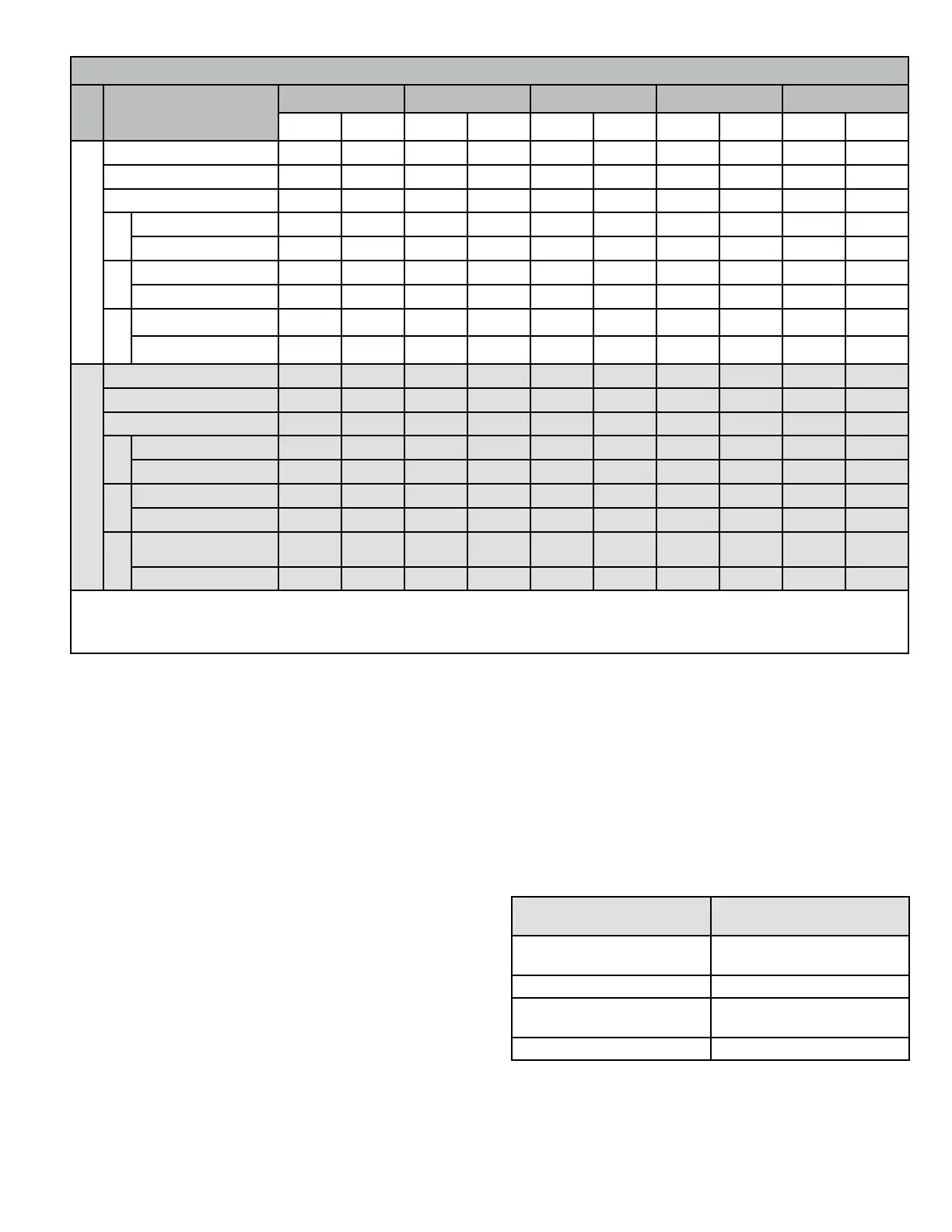
Airow Performance as a Function of External Static Pressure
Model
Indoor Blower Speed
0.1 “w.c. 0.2 “w.c. 0.3 “w.c. 0.4 “w.c. 0.5 “w.c.
SCFM Watts SCFM Watts SCFM Watts SCFM Watts SCFM Watts
*MHP4-11-301*P
TAP 1 (FAN) 590 43 535 48 430 55 380 60 315 65
TAP 2 (COOL/HP)
†
1040 161 1005 169 970 177 935 185 900 193
TAP 3 (COOL/HP) 1135 201 1105 211 1070 220 1040 229 1010 237
5 kW
TAP 4 (AUX HEAT)* 1075 151 1040 159 1005 168 N/A N/A N/A N/A
TAP 5 (AUX HEAT) 1165 181 1135 193 1100 205 1065 216 1025 225
7 kW
TAP 4 (AUX HEAT)* 1075 151 1040 159 1005 168 N/A N/A N/A N/A
TAP 5 (AUX HEAT) 1165 181 1135 193 1100 205 1065 216 1025 225
10 kW
TAP 4 (AUX HEAT)* 1075 151 1040 159 1005 168 N/A N/A N/A N/A
TAP 5 (AUX HEAT) 1165 181 1135 193 1100 205 1065 216 1025 225
*MHP4-11-361*P
TAP 1 (FAN) 680 61 630 68 575 74 525 79 460 86
TAP 2 (COOL/HP)
†
1235 260 1200 272 1165 284 1135 295 1100 305
TAP 3 (COOL/HP) 1315 304 1280 316 1250 330 1215 342 1180 354
5 kW
TAP 4 (AUX HEAT)* 1240 232 1205 248 1170 262 N/A N/A N/A N/A
TAP 5 (AUX HEAT) 1340 283 1290 300 1260 315 1230 328 1200 338
7 kW
TAP 4 (AUX HEAT)* 1240 232 1205 248 1170 262 N/A N/A N/A N/A
TAP 5 (AUX HEAT) 1340 283 1290 300 1260 315 1230 328 1200 338
10 kW
TAP 4 (AUX HEAT)* 1240 232 1205 248 1170 262 N/A N/A N/A N/A
TAP 5 (AUX HEAT) 1340 283 1290 300 1260 315 1230 328 1200 338
N/A: Do not operate unit using this blower speed at this external static pressure.
† As shipped speed for Cooling operation. Blower speed must be eld adjusted to Speed Tap 3 for higher duct static applications.
* As shipped speed for Heating operation. Blower speed must be eld adjusted to Speed Tap 5 for higher duct static applications.
Table 3. Blower Performance (208V or 230V)
Air Filter
All indoor return air must be ltered. A washable lter is
furnished with the unit, located in the return air compartment.
If the optional front return opening is used and a duct is
installed, provisions must be made to accommodate lter
servicing. If a lter is installed at a separate central return
location, then the factory furnished lter must be removed
from the unit.
The lter should be cleaned at least three times during
each of the heating and cooling seasons, or more
frequently if unusual conditions are encountered. To clean
the washable lter, shake lter to remove excess dirt and/
or use a vacuum cleaner. Wash lter in soap or detergent
water and replace after lter is dry. It is not necessary to oil
the lter after washing.
The washable lter may be replaced with a disposable
lter. Table 4 lists lter sizes that t the unit.
If an installation is made in which it is more desirable to
mount the lter exterior to the unit, in the return duct work
or elsewhere, the washable lter can be used or replaced
with a disposable lter. If a disposable lter is used, use the
information provided in Table 5 when sizing the disposable
lter.
Model Number
Filter Size
(in.)
*MHP4-11-09*
*MHP4-11-12*
18 x 20 x 1
*MHP4-11-18* 20 x 20 x 1
*MHP4-11-24*
*MHP4-11-30*
22 x 24 x 1
*MHP4-11-36* 22 x 28 x 1
Table 4. Filter Sizes
 Loading...