Page 8 of 17 507861-01Issue 1927
Model Number
Filter Area
(in
2
)
*MHP4-11-09*
*MHP4-11-12*
265
3MHP4-11-18*
5MHP4-11-18*
310
7MHP4-11-18*
10MHP4-11-18*
360
*MHP4-11-24* 400
*MHP4-11-30* 515
*MHP4-11-36* 600
Table 5. Minimum Required Surface Area for
Disposable Filters
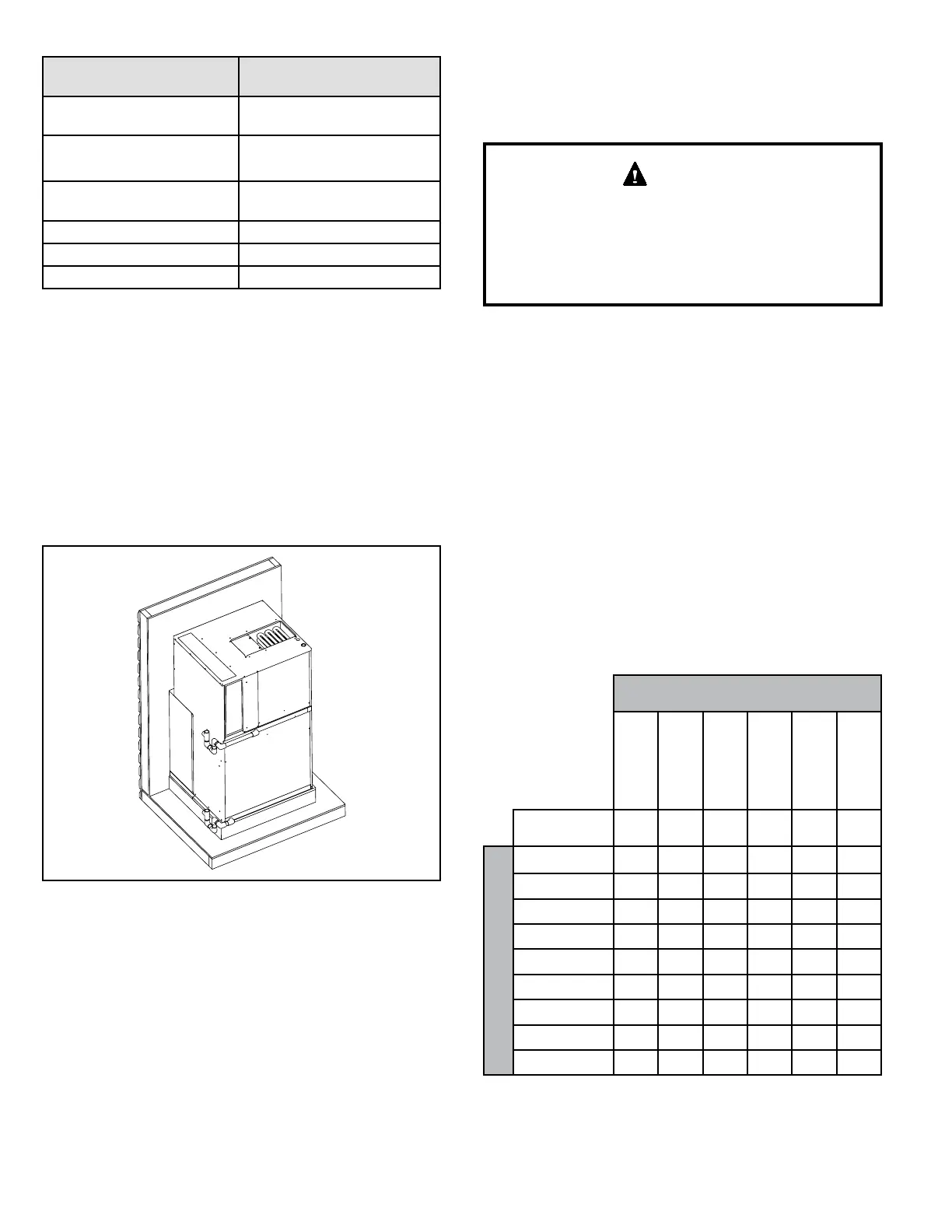
Condensate Drain
Provisions must be made to properly drain the indoor and
outdoor drain pans of this appliance.
Indoor drain and outdoor drain connection: 3/4” NPT to
3/4” PVC tting (schedule 40 minimum). Both drains must
be trapped as shown in Figure 6. The drain line should
pitch gradually downward at least 1” per 10’ of horizontal
run to an open drain.
Figure 6. Condensate Drain Installation
If local codes require the use of metal condensate lines,
do not thread metal ttings into the unit drain pans. Thread
a PVC tting into the unit drain pans and make the eld
connection to the PVC tting.
NOTE: MHP units are designed with a redundant drain
system to handle condensate without the need for a
secondary or emergency drain pan. Should the indoor
coil condensate drain system fail, all water is contained
within the unit and the ow is directed into the unit base
pan. From there it will drain into the condensate riser.
If for some reason the water cannot drain into the main
condensate riser, all water is contained in the unit, and the
design will allow drainage out through the wall sleeve and
louver assembly to the outside of the building.
Use thread sealant on the threaded ttings. Install
threaded ttings by hand only. Do not over torque the
ttings.
Do not thread metal condensate ttings to unit drain
pans.
CAUTION
Outdoor Ventilation Air
Units are tted with a panel that seals the return air
compartment at the outdoor air duct. If introduction of
outdoor air is desired, installers can replace the factory-
installed panel with the provided auxiliary panel by removing
screws holding both the factory and auxiliary panels, and
then replacing with the auxiliary panel and screw.
NOTE: If outdoor ventilation air is introduced, the quantity
of air and conditions of this air must be accounted for in the
load calculations for the unit installation.
The auxiliary panel includes nine knockouts to congure
air ow to installation requirements. Use Table 6 and
Figure 7 to determine which knockouts to remove from the
auxiliary panel in order to achieve the desired air ow. Use
a at head screw driver to remove the knockouts. Set the
factory-installed panel aside for possible future changes.
Outdoor Ventilation Air
(CFM)
*MHP4-11-09*
*MHP4-11-12*
*MHP4-11-18*
*MHP4-11-24*
*MHP4-11-30*
*MHP4-11-36*
Nominal
Indoor Airow
350 475 600 800 1025 1200
Number of Openings
#1 Only 6 11 13 18 20 23
#1 and #2 10 17 21 24 28 31
#1 thru #3 17 22 26 32 36 41
#1 thru #4 23 28 35 41 45 49
#1 thru #5 31 34 42 50 55 60
#1 thru #6 35 41 49 57 66 72
#1 thru #7 41 49 56 68 80 86
#1 thru #8 46 56 64 78 88 98
#1 thru #9 50 60 73 90 100 112
Table 6.
 Loading...