PARTS LIST
2
TOOLS REQUIRED
Item Description Qty. Part No.
A Stair climber 2 304285
B Frame spacer 2 304282
C Lower bracket 2 304284
D Axle spacer 2 304283
E Pan head machine screw - 1/4"-20 x 1-7/8" long 2 80039
F Pan head button hex socket screw - 5/16"-18 x 1-1/2" long 2 80155
G Hex lock nut - 1/4"-20 2 80675
H Hex lock nut - 5/16"-18 2 80676
I Washer - 5/16" ID x .100" thick 2 80739
• PLIERS
• #3 PHILLIPS SCREWDRIVER
• (1) 7/16" WRENCH
• (2) 1/2" WRENCHES
• (1) 9/16" WRENCH
• 3/16" ALLEN WRENCH
• DRILL MOTOR
• Ø .281 (K) DRILL BIT
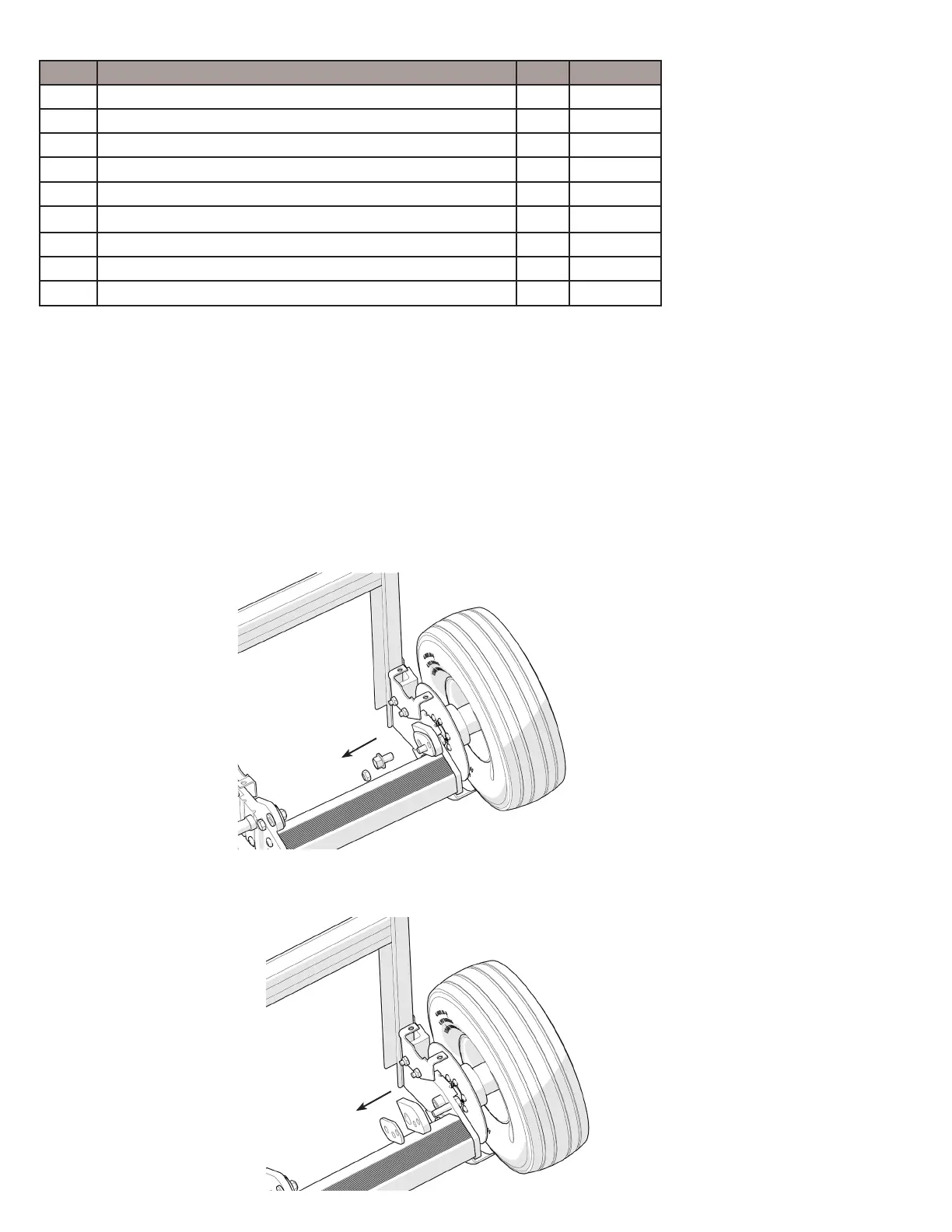
Step 1
Remove lock nut and axle bolt shown below. Keep lock nut and axle bolt.
Please note - brake caliper and
brake line not shown for simplicity.
Step 2
Remove the existing spacers.
(1/2" wrenches, 9/16" wrench and pliers)
Note: These instructions are for Hydraulic Brake Trucks with the dual stub-axle (design prior to October 2019). If your
brake truck has a single through-axle (current truck design from October 2019 and later) please download instructions
from www.magliner.com/tools-resources/assembly-instructions.
If you would like to convert your brake truck from dual stub-axle to single through-axle design, order 221541 axle conver-
sion kit.
Use a workbench or table of convenient height and place all components in view and within reach. It may be helpful to
work with the hand truck oriented face down. The following assembly sequence is recommended: