EasyManua.ls Logo

Magliner C5 - User Manual

Magliner C5
4 pages
Print Icon
To Next Page IconTo Next Page
Loading...
www.magliner.com
ASSEMBLY INSTRUCTIONS
Table of Contents:
Parts List .................................... 2
Assembly Instructions ...........2-4
C5 Stair Climbers
Hydraulic Brake Truck
For safe, efficient product use, Magline recommends inspecting
equipment regularly and replacing damaged components
immediately.
Question and Answer IconNeed help?

Do you have a question about the Magliner C5 and is the answer not in the manual?

Summary

Assembly Instructions

Parts List

List of components required for the hydraulic brake truck assembly, including item, description, quantity, and part number.

Tools Required

List of tools necessary for the assembly process, such as pliers, screwdrivers, and wrenches.

Step 1: Remove Lock Nut and Axle Bolt

Initial step to remove the lock nut and axle bolt from the existing setup, keeping them for reuse.

Step 2: Remove Existing Spacers

Instruction to remove the current spacers from the assembly, preparing for new component installation.

Step 3: Install Lower Bracket and Axle Spacer

Attaching the lower bracket and axle spacer, with guidance on temporary bolt placement for alignment.

Step 4: Install C5 Stair Climber

Mounting the C5 stair climber using specific bolts, washers, and lock nuts, finger-tightening initially.

Step 5: Connect C5 Stair Climber to Frame

Securing the C5 stair climber to the frame, potentially requiring hole creation for 60" frames.

Step 6: Final Tightening

Final tightening of hardware installed in Step 4 to specified torque values.

Overview

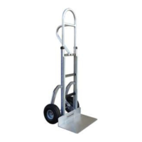
This document provides assembly instructions for the Magliner C5 Stair Climbers Hydraulic Brake Truck. It details the steps required to install the stair climber components onto a hand truck, specifically for models equipped with a dual stub-axle design (prior to October 2019). For trucks with a single through-axle (October 2019 and later design), users are directed to download alternative instructions from the Magliner website. An axle conversion kit (part number 221541) is available for those wishing to convert a dual stub-axle brake truck to a single through-axle design.

Function Description:

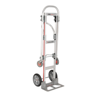
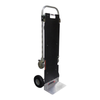
The C5 Stair Climbers are designed to enhance the functionality of Magliner hand trucks, particularly those with hydraulic brakes, by enabling easier navigation up and down stairs. These stair climbers provide a mechanism that assists in maneuvering heavy loads over steps, reducing strain on the operator and improving efficiency. The assembly process involves attaching specialized brackets, spacers, and the stair climber units themselves to the hand truck's frame and axle.

Important Technical Specifications:

The assembly requires specific tools and hardware, all detailed in the "PARTS LIST" and "TOOLS REQUIRED" sections.

Parts List:

  • A: Stair climber (Qty: 2, Part No: 304285) - The main stair climbing unit.
  • B: Frame spacer (Qty: 2, Part No: 304282) - Used to create space between components on the frame.
  • C: Lower bracket (Qty: 2, Part No: 304284) - Supports the stair climber near the axle.
  • D: Axle spacer (Qty: 2, Part No: 304283) - Used to space components on the axle.
  • E: Pan head machine screw - 1/4"-20 x 1-7/8" long (Qty: 2, Part No: 80039) - Fastens components to the frame.
  • F: Pan head button hex socket screw - 5/16"-18 x 1-1/2" long (Qty: 2, Part No: 80155) - Secures the stair climber to the lower bracket.
  • G: Hex lock nut - 1/4"-20 (Qty: 2, Part No: 80675) - Used with screw E.
  • H: Hex lock nut - 5/16"-18 (Qty: 2, Part No: 80676) - Used with screw F.
  • I: Washer - 5/16" ID x .100" thick (Qty: 2, Part No: 80739) - Used with screw F.

Tools Required:

  • Pliers
  • #3 Phillips Screwdriver
  • (1) 7/16" Wrench
  • (2) 1/2" Wrenches
  • (1) 9/16" Wrench
  • 3/16" Allen Wrench
  • Drill Motor
  • Ø .281 (K) Drill Bit (for 60" frames)

Torque Specifications:

  • Axle bolt: 50 ft.-lbs. torque (after applying blue thread locker).
  • Lock nut (for axle bolt): 100-120 in.-lbs. torque.
  • Hardware in Step 5 (screw E, spacer B, lock nut G): 50-60 in.-lbs. torque.
  • Hardware in Step 4 (bolt F, washer I, lock nut H): 100-120 in.-lbs. torque.

Usage Features:

The assembly process is broken down into six steps, designed for clarity and ease of installation.

  • Step 1: Initial Disassembly - Involves removing the existing lock nut and axle bolt, which are to be retained for later use. This step requires 1/2" wrenches, a 9/16" wrench, and pliers.
  • Step 2: Spacer Removal - Existing spacers on the axle are removed to make way for the new components.
  • Step 3: Bracket and Spacer Installation - The lower bracket (C) and axle spacer (D) are inserted. A helpful tip suggests temporarily inserting a screw through both spacers to maintain alignment before tightening the lock nut and axle bolt. Blue thread locker is applied to the axle bolt threads before tightening. This step requires 1/2" wrenches, a 9/16" wrench, pliers, and blue thread locker.
  • Step 4: Stair Climber Attachment - The C5 stair climber (A) is installed using a pan head button hex socket screw (F), washer (I), and hex lock nut (H). The wheel needs to be rotated to allow the bolt to pass through a cutout in the rotor. This step requires a 3/16" Allen wrench and a 1/2" wrench. Initial tightening is finger-tight only.
  • Step 5: Frame Connection - The C5 stair climber is rotated upward to meet the frame. Depending on the frame size (39" or 60"), a hole may need to be punched or drilled in the frame. A pan head machine screw (E), frame spacer (B), and hex lock nut (G) are then installed and tightened. This step requires a 7/16" wrench and a #3 Phillips screwdriver, and for 60" frames, a drill motor and Ø .281 (K) drill bit.
  • Step 6: Final Tightening - The hardware installed in Step 4 is fully tightened to the specified torque.

Throughout the instructions, "Please note - brake caliper and brake line not shown for simplicity" is mentioned, indicating that these components are present on the actual truck but omitted from the diagrams for clearer illustration of the stair climber assembly.

Maintenance Features:

The manual emphasizes the importance of regular inspection and timely replacement of damaged components for safe and efficient product use. This proactive approach to maintenance ensures the longevity and reliable performance of the Magliner C5 Stair Climbers. The use of blue thread locker on the axle bolt threads in Step 3 is a specific maintenance-related instruction to prevent loosening of critical fasteners over time.

Magliner C5 Specifications

General IconGeneral
BrandMagliner
ModelC5
CategoryTrucks
LanguageEnglish

Related product manuals