Setup Page: 15 3.0 Setup Overview of how to configure the ME-ARC remote to control inverter/charger parameters.
CTRL: 01 ACIn Control Configuration settings for when the inverter/charger connects to an incoming AC power source.
METER: 02 AC Meters Details on AC voltage and frequency readings available from the METER button.
METER: 03 Timers Information on timers related to charger operation, such as charge time and since EQ start.
SETUP: 01 System Setup Menus for setting up the remote's screen and real-time clock for proper feature operation.
01A Set Clock Procedure for setting the ME-ARC's internal real-time clock for accurate operation.
01B Screen Setup Settings for adjusting LCD screen contrast, brightness, and power save features.
01C Temp Display Option to select temperature display units as Fahrenheit or Celsius for various menus.
02A Search Watts Setting to adjust the power level that determines when the inverter leaves Search mode.
02B LBCO Setting Configuration for the Low Battery Cut Out voltage level to protect batteries from over-discharge.
02C AC In - Time Setting to connect to utility power at a predetermined time of day for cost savings.
02D AC In - VDC Determines when the inverter automatically connects/disconnects utility power based on battery voltage.
02E AC In - SOC Determines when the inverter connects/disconnects utility power based on battery State of Charge.
03A AC Input Amps Setting to ensure combined current draw does not exceed the maximum incoming AC power.
03B VAC Dropout Sets the minimum AC voltage required on the input for the inverter/charger to connect to AC.
03C Battery Type Selects the battery type to ensure proper charge profile and voltage settings.
Set CV Charge Volts Sets the voltage level for holding batteries during the Constant Voltage stage.
Set CV Chg Done Determines when the Constant Voltage stage of charging is finished, transitioning to Silent stage.
Set CV Chg Done Time Sets a specific time to determine when the Constant Voltage charge cycle should end.
Set CV Chg Done Amps Uses DC amperage to determine when the Constant Voltage charge cycle should end.
Set Max CC/CV Time Safety feature setting the maximum time charger operates in CC or CV modes.
Set Recharge Volts Sets the DC voltage set-point to which batteries fall before charger restarts charging.
Absorb Volts Sets the voltage level held constant during the Absorption charge cycle.
Float Volts Sets the voltage level held constant during the Float charge cycle.
EQ Volts Sets the voltage level held constant during the Equalization charge cycle.
EQ Done Time Sets the duration the battery charges at the EQ Volts setting.
03E Max Charge Rate Sets maximum charge rate to prevent battery overheating, expressed as a percentage.
03F Max Charge Time Safety feature limiting maximum time charger operates in Bulk, Absorption, or EQ modes.
03H EQ Reminder Days Sets the number of days before the remote reminds you to equalize your batteries.
TECH Button and Menus Accessing technical information and settings for troubleshooting and system diagnostics.
TECH: 01 Temperatures Displays various temperatures measured throughout the system (inverter, AGS, ACLD, PT).
TECH: 02 Versions Displays software versions of connected devices (inverter, remote, AGS, BMK, ACLD, PT).
04A Inv Faults Displays a history of the last nine inverter/charger faults with detailed information.
04D Clear Faults Allows clearing of all recorded fault history for connected devices.
TECH: 05 SETUP PIN Sets a password (PIN) to lock/unlock the ARC's SETUP button menus for security.
TECH: 06 Ext Control Read-only menu to check if external devices are controlling inverter/charger functions.
Operation Page: 52 5.0 Operation Explanation of how to operate the inverter/charger using the ME-ARC remote.
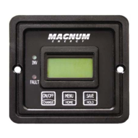
5.1 Front Panel Description of the ME-ARC front panel components: LEDs, LCD, buttons, and rotary knob.
5.1.1 LED Indicators Guide to understanding the status indicated by the four LED indicators on the front panel.
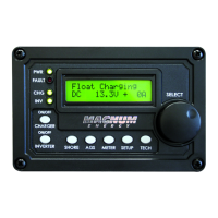
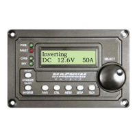
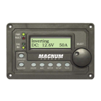
5.1.2 LCD Display Explanation of the LCD display's role in showing status, fault conditions, and setup menus.
5.1.4 Menu Buttons Overview of the five menu buttons (FAVS, CTRL, METER, SETUP, TECH) for system access.
5.2.1 Inverter Mode How to turn the inverter on/off, understanding Inverting, Searching, and Standby modes.
5.2.2 Charger Mode Description of how the charger mode activates and the various statuses it can display.
Equalizing Explanation of the controlled overcharge process to mix electrolyte and remove sulfates.
AC Backfeed Troubleshooting steps for AC backfeed faults, indicating AC voltage on the output.
AC Overload Troubleshooting steps for AC overload faults when output current exceeds protection limits.
Breaker Tripped Troubleshooting steps for AC input breaker trips due to excess current flow.
Dead Batt Charge Troubleshooting steps for faults indicating a dead or disconnected battery bank.
FET Overload Troubleshooting steps for FET over-temperature faults indicating abnormal component heating.
High Battery Troubleshooting steps for high battery voltage faults that cause the inverter to shut down.
High Batt Temp Troubleshooting steps for faults related to the Battery Temperature Sensor (BTS) overheating.
High Speed Bus Troubleshooting steps for communication errors between internal microprocessors.
High Volts AC Troubleshooting steps for high AC input voltage faults that disable the AC input.
Low Battery Troubleshooting steps for low battery faults that turn off the inverter to prevent over-discharge.
Overcurrent Troubleshooting steps for faults caused by excessive AC load on internal power components.
Overtemp Troubleshooting steps for faults when internal components exceed safe temperature operating range.
Stuck Relay Troubleshooting steps for faults where the AC pass-thru relay is abnormally closed during inverting.
Tfmr Overtemp Troubleshooting steps for transformer over-temperature faults protecting the internal transformer.
Unknown Fault ## Troubleshooting steps for faults with unrecognized codes, requiring technical support.
Using a PT Controller: Setup Page: 99 06A Battery Type Selects the battery type, determining the charge profile and voltage settings.
Set Max Charge Amps Sets maximum charge amperage to limit current and prevent battery overheating.
Set CV Charge Volts Sets the voltage level at which the charger holds batteries during Constant Voltage stage.
Set CV Chg Done Determines when the Constant Voltage stage finishes, transitioning to Silent stage.
Set CV Chg Done Amps Uses minimum current (return amps) to determine when the Constant Voltage charge ends.
Set Max CC/CV Time Safety feature setting maximum time for CC or CV charge modes to prevent prolonged high voltage.
Set Recharge Volts Sets the DC voltage set-point for batteries to fall to before charger restarts.
Absorb Volts Sets the voltage level held constant during the Absorption charge stage.
Float Volts Sets the voltage level held constant during the Float charge stage.
EQ Volts Sets the voltage level held constant during the Equalization charge stage.
EQ Done Time Sets the duration for battery charging at the EQ Volts setting.
Set Absorb Done Amps Uses minimum current (return amps) to determine when batteries are fully charged.
Set Absorb Done SOC Uses battery State of Charge (SOC) to determine when batteries are fully charged.
06C Max Charge Rate Sets maximum charge rate to prevent battery overheating, expressed as a percentage.
06D Max Charge Time Safety feature limiting maximum time controller operates in Bulk, Absorption, or EQ modes.
06E Bulk Start Allows PT controller to automatically start a Bulk charge cycle based on various conditions.
Daily/SunUp Option to set the PT controller to start Bulk charge cycle each new day at sun-up.
Volts Sets the DC voltage level that will start the Bulk charge cycle when battery voltage decreases.
SOC Sets the battery's SOC level to start the Bulk charge cycle, using the BMK monitor.
06F PT Aux Relay Programs the Aux Relay to engage or disengage based on battery voltage or PT controller fault.
06G PT Alarm Programs the alarm to turn on/off based on battery voltage or PT controller fault.
Using a PT Controller: Troubleshooting Page: 116 ARC Fault-PT Troubleshooting steps for detecting and clearing DC arc faults on the PV input.
BTS Open-PT Troubleshooting steps for BTS sensor open or disconnected faults.
FET Overtemp-PT Troubleshooting steps for internal FET over-temperature faults.
Ground Fault-PT Troubleshooting steps for ground fault conditions that cause the GFP fuse to open.
HiBatt Temp-PT Troubleshooting steps for high battery temperature faults detected by the BTS.
High Bat VDC-PT Troubleshooting steps for high battery voltage faults detected on the battery input terminals.
High PV VDC-PT Troubleshooting steps for very high PV voltage faults detected on the PV input terminals.
Ind Overtemp-PT Troubleshooting steps for internal inductor over-temperature faults.
Int Hardware-PT Troubleshooting steps for redundant hardware protection circuit faults.
Int NTC-PT Troubleshooting steps for faults detected by the internal NTC temperature sensor.
Int Overload-PT Troubleshooting steps for faults where internal sensor current exceeds protection limits.
Int Phase-PT Troubleshooting steps for faults related to faulty internal phases or out-of-sync signals.
Int Power-PT Troubleshooting steps for faults when internal power control circuitry reaches protection limits.
Int Pwr Sup-PT Troubleshooting steps for faults related to low auxiliary power supply voltage.
No PV Input-PT Troubleshooting steps for faults when no PV power is detected for over 24 hours.
Unknown Fault ## Troubleshooting steps for faults with unrecognized codes, requiring technical support.