D-5
35 Series 4WD, Model - 3535, 4035, 4535 and 5035 SM June’08
Clutch
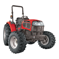
Fig. 3
Fig. 1
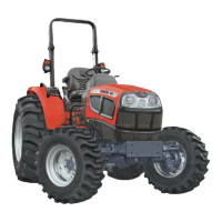
3. SINGLE PLATE DIAPHRAGM CLUTCH
The single plate clutch is a foot operated dry plate type.
It consists of a driven plate assembly, cover assembly
and a release bearing assembly. The driven plate
assembly is clamped between the flywheel rear face
and the cover assembly which is bolted to the flywheel.
The cover assembly is composed of compress steel cover,
a diaphragm, a pressure plate, a belleville washer, return
spring and antidrop rivets and clutch assembly mounting
bolts with washer. The cover assembly is bolted to the
flywheel. The diaphragm is made of spring steel, a flat
spring or belleville washer fingers are cut out in the
center. When assembled to the cover the diaphragm
is pressed to create tension in spring and load the
pressure plate.
A tangential drivestrap (7-2) maintain the diaphragm
against the fulcrum in the cover (C P type cover).
The pressure plate is held against the diaphragm by
return spring. The return springs are fasten by rivets
(6-2) to the cover and pressure plate. Antidrop rivets
are provided to prevent excessive movement of pressure
plate.
4. REMOVAL
1. To remove the clutch engine must be separated
from the clutch housing. Apply parking hand brake
and wedge to rear tire.
2. For spliting the tractor between clutch housing
and engine refer the procedure as detailed in
“Spliting The Tractor”.
3. Punch the mark matching clutch cover and
flywheel position to ensure that the clutch is
installed in its original position.
4. Remove the cap screws securing the clutch cover
assembly to the flywheel for single plate clutch
ref. (fig.1).
5. DISMANTLING
a) Gently pierce out (by drilling) both end of the drive
strap rivet and remove pressure plate from the
cover assembly.
NOTE:
1. Ensure that the hole on the pressure plate
and cover are not damaged.
2. Before doing drilling of operating clamp the
job should be hold properly to avoid
movement.
Use service fixture as shown in the figure
to do the assembly of pressure plate and
drive strap. Use press to rivet the drive strap
and pressure plate securely.
b) Pierce out (by drilling) cover rivets and remove
pressure plate sub assembly.
c) Then gently pierce out (by drilling) delta rivet
riveted head and remove diaphragm.
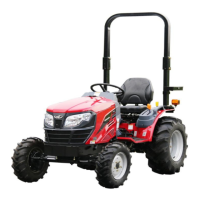
Fig. 2
1. Clutch housing 5. Pin
2. Pressure plate 6. Pivot
3. Diaphragm spring 7. Tangential drive strap
4. Ring 8. Balance hole
 Loading...