C-33
35 Series 4WD, Model - 3535, 4035, 4535 and 5035 SM June’08
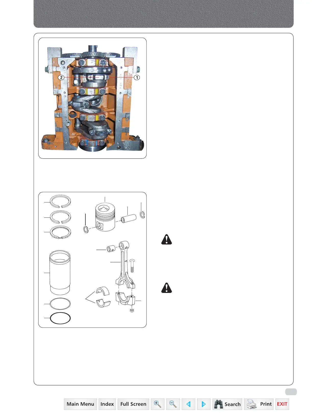
Fig. 1
Fig. 2
1. DESCRIPTION
The I-section connecting rods are forged steel and carry
a bronze bush at the small end for installation of the
piston pins. The big end is mounted on the crankshaft
over steel backed alloy replaceable bearing inserts.
The big end bearing caps for each connecting rod are
matched fit and the matching parts are numbered to
ensure correct assembly.
2. CONNECTING ROD AND PISTON ASSEMBLY
a) REMOVAL :
1) Remove the cylinder head.
2) Remove the carbon ridge at the top of each sleeve.
3) Remove all the bolts securing the oil pan to the
crankcase and pull out the oil pan. Remove the
gasket from the crankcase and discard it.
4) Remove the bolt securing the oil pump to the
crankcase and carefully withdraw the oil pump.
Take care not to damage the teeth in the pinion
gear.
5) Take off connecting rod bearing caps (2-1) with
bearings and lift out pistons with connecting rods,
by pushing up and out of the sleeve.
6) Replace inserts (9-2) in bearing caps (8-2) on
connecting rods to prevent mixing up.
7) With long-nose pliers remove piston pin retainer
springs by squeezing pronged ends, fig. 4.
NOTE: If the cylinder sleeve has been worn so that
there is a ridge in the sleeve at the upper end
of the piston travel, this must be removed
before the piston is withdrawn, to prevent
damage to the ring lands and rings during
removal of piston.
3. INSPECTION AND REPAIRS :
NOTE:
i) Do not hold the piston in a vice.
ii) Always service/change the piston and piston
pin as a set.
iii) It is advisable that, whenever the piston and
the connecting rod assembly is removed
from the sleeve new piston rings be installed
while re-assembling.
a) Check the piston ring grooves for wear, using new
ring and feeler gauges (Fig. 5). See specifications
for acceptable clearance.
b) Check the pistons for seizure or/and overheating
marks.
1. Sleeve
2. ‘O’ Ring Top-Red
3. ‘O’ Ring Bottom-Black
4. Piston
5. Pin
6. Circlip
7. Connecting Rod
8. Conn. Rod Cap
9. Conn. Rod Bearing
10. Conn. Rod Small
End Bush
11. Compression Ring
12. Compression Ring
13. Oil Ring
10
9
8
7
11
12
13
Connecting Rods, Pistons & Cylinder Sleeves
1
2
3
6
4
5
6