38
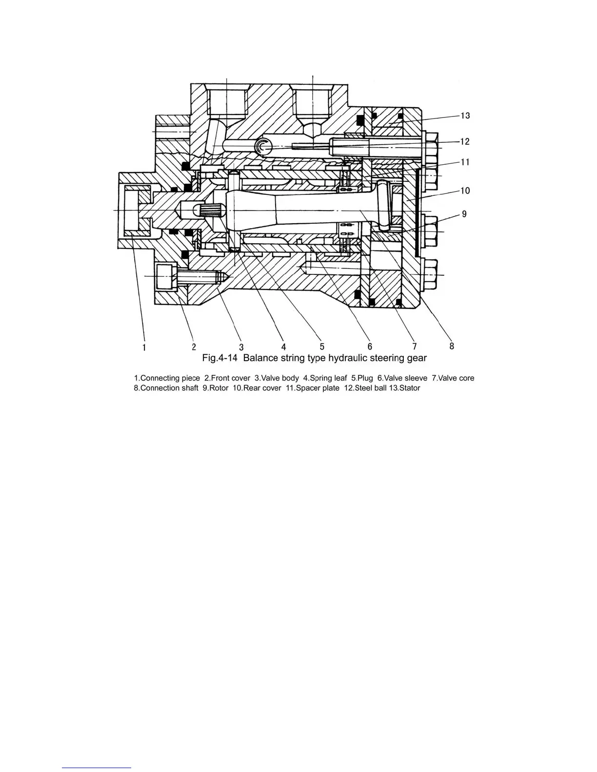
Valve sleeve of the steering control valve (6) is connected with valve core (7) through
plug (5), and spring leaf is fixed in the middle of the valve. The hole in the valve core (for
mounting the plug) is a little bigger than the hole in valve sleeve (6), so they can rotate
relatively, the outside of the valve core connects with connecting piece (1).
The stator (13) and rear cover (10) of steering measuring device are fixed together with
valve body (3) of steering control valve by bolt. Rotor (9) connects with valve sleeve (6)
through connection shaft (8) and plug (5). Rotor (9) and stator (13) are balance string type
needle wheel mesh pair. The rotor has 6 short outer pendulum string curve teeth of equal
distance, while the stator has 7 arc needle teeth. During working, the stator is still and the
rotor rotates round the center of the stator at the radius of a certain eccentric distance. When
the rotor rotates round center of the stator (revolution), it also rotates round its axial line in
opposite direction (rotation). As the rotor makes a circuit and it can rotates round the stator
center for -6/(7-6)=-6 circuits, rotor makes one circuits, the oil liquid will be squeezed out
×
from the teeth slot (6 7=42), and the displacement at unit volume is large.
B. Adjustment of balance string type hydraulic steering gear.
As the rotating times or circuits of the steering wheel concern the rated displacement of
 Loading...