©2015 - Compiled by Robert Anselmi Reason101.net
Visit www.makenoisemusic.com for full manual
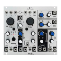
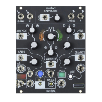
Make Noise DPO Complex Dual VCO Module
The DPO is a dual VCO designed for generating complex waveforms and implementing FM synthesis in the analog domain. Expanding on the classic arrange-
ment of primary and mod oscillators, the DPO has both of the VCOs operable as complex signal sources. It is, in essence, a Dual Primary Oscillator. Dynamic
FM, Circular FM, Hard Sync and Additive Harmonic synthesis processes are all achieved with internal routing on the DPO. The DPO has two modulation buses
(Mod & FM), each with multiple destinations, the depth of which is adjustable per destination. The DPO is a 100% analog, vintage voiced musical instrument.
OSCILLATOR
A WAVEFORM
OUTS: Triangle
wave output.
10Vpp. Sawtooth
wave output.
9Vpp. Sine wave
output. 10Vpp.
SHAPE ROTARY, SHAPE CV IN & ATEN-
UATOR: The Shape Rotary is a unipolar control
that determines the shape of the waveform feed-
ing the Fold circuit. Morphs from Sine to Spike to
Glitched Triangle. The Shape CV In is a unipolar
control signal input normalled into the Mod Bus.
Range: 0V to +5V. The Shape Attenuator is a
unipolar level control for the Shape CV Input.
OSCILLATOR B
WAVEFORM OUTS:
Sine wave output.
10Vpp. Square wave
output. 9Vpp. Final wave
output is processed by
the Shape, Angle & Fold
circuits. 10Vpp.
ANGLE ROTARY, AN-
GLE CV IN & ATTENU-
ATOR: The Angle Rotary
tilts the added harmonics to
either end of the wave-cycle.
The Angle CV In is a bipolar
control signal input normalled
into the Mod Bus. Range: 8V.
The Angle Attenuator is a
unipolar level control for the
Angle CV Input.
FOLD ROTARY, FOLD
CV IN, FOLD ATTENU-
ATOR & STRIKE GATE IN: The Fold Rotary
is a unipolar control that continuously varies the
low-order harmonics of the signal by folding the
waveform into itself. Fold CV In is a unipolar control
signal input normalled into the Mod Bus. Fold At-
tenuator is a unipolar level control for the Fold CV
Input. The Strike Gate In, when patched, briey
opens the Fold circuit to 100%. Requires an 8V -
10V gate or clock to operate.
VCO A COARSE TUNE RO-
TARY: Controls coarse tuning for
oscillator A frequency. Range: 9.5
octaves; 12hz-6khz.
VCO B COARSE TUNE
ROTARY & VCO B 1V/
OCT SCALE TRIM: Con-
trols coarse tuning for oscil-
lator B frequency. Range: 9.5
octaves; 12hz-6khz. The 1V/
Octave Scale Trim control is
used to calibrate VCO B.
VCO A FINE TUNE ROTARY:
Controls ne tuning for oscillator A
frequency. Range: 1.75 octaves.
VCO B FINE TUNE RO-
TARY: Controls ne tuning
for oscillator B frequency.
Range: 1.75 octaves.
VCO A 1V/OCT SCALE TRIM:
Used to calibrate VCO A.
VCO A 1V/OCTAVE CV IN:
Bipolar pitch control for VCO A.
Optimal range: +/-5V.
VCO B 1V/
OCTAVE CV IN:
Bipolar pitch control
for VCO B. Optimal
range: +/-5V.
VCO A EXPONENTIAL CV IN
& ATTENUATOR: Bipolar expo-
nential frequency CV input for VCO
A. Normalled to FM Bus. Range:
10V. The associated Exponential
Attenuator acts as a unipolar level
control for the Exponential CV Input.
VCO B EXPONENTIAL CV IN & ATTENUATOR: Bipolar exponen-
tial frequency CV input for VCO B. Normalled to FM Bus. Range: 10V. The
Exponential Attenuator acts as a unipolar level control for the CV Input.
MOD BUS INDEX ROTARY, EXTERNAL SOURCE IN,
INDEX IN, ATTENUVERTOR & LED: The Mod Bus Index
Rotary is a unipolar control that sets the depth of the Mod Bus.
The Mod Bus External Source Input interrupts internal routing
of VCO A sine wave as a modulation source. Range: +/- 8V. The
Mod Bus Index CV Input is a bipolar CV input signal. Range:
+/- 4V. The associated Mod Bus Index Attenuvertor acts as a
bipolar level control for the Mod Bus Index CV Input. The Mod
Bus Index LED provides visual indication of the currently pro-
grammed Mod Index value.
FM BUS ROTARY, INDEX CV IN, ATTENUVER-
TOR & LED: The FM Bus Rotary is a unipolar control
that sets the depth of the FM. The FM Bus Index CV Input
is a bipolar CV input. Range: +/-4V. The FM Bus Index
Attenuvertor acts as a bipolar level control for the FM Bus
Index CV Input. The FM Bus Index LED provides visual
indication of the currently programmed FM Index value.
FOLLOW CV IN & ATTENU-
ATOR: The Follow CV Input is a
unipolar control. Range: 0V to 5V. The
Follow Attenuator determines how
well VCO A follows VCO B. With noth-
ing patched to Follow CV In, it acts as
a standard control. When patched, it
acts as an attenuator for that signal.
BEAT FRE-
QUENCY
LED: Provides
visual indication
of the phase
difference
between VCOs
A & B.
VCO A LINEAR CV IN & ATTENUATOR:
Unipolar linear frequency CV input for VCO A.
AC coupled. Normalled to FM Bus. Range: 10V.
The associated Linear Attenuator acts as a
unipolar level control for the Linear CV Input.
VCO B LINEAR CV IN, LINEAR ATTENUATOR & EXTERNAL LOCK
IN: Unipolar linear frequency CV input for VCO B. AC coupled. Normalled to FM
Bus. Range: 10V. The associated Linear Attenuator acts as a unipolar level
control for the Linear CV Input. External Lock In allows VCO B to be phase
locked to a hard-edged signal (square, pulse or Sawtooth) from other VCOs.
VCO MODE BUTTON: Cycles
between 4 modes (indicated by
LED): No LED: Standard, Lock
(Blue LED): VCO A is phase locked
to VCO B. Sync (Pink LED): VCO
A is Hard Synced to VCO B. LFO
(Amber LED): VCO A acts as a low
frequency oscillator.
Follow: Follow is useful in maintaining FM or Sync ratios while controlling the DPO with a sequencer or keyboard. The lag that occurs when Follow is set to
less than 100% will introduce moments of dissonance and noise, due to the temporary tracking errors. This is a wonderful way to introduce uncertainty to an
otherwise stable sequence of notes.
FM Bus: The internal FM bus is hardwired for Sine wave in both directions. With nothing patched to the Linear and/or Expo FM inputs, the associated
attenuator sets the nal index of FM applied to each destination. As you increase the Index level, the amplitude of VCO A sine bused to VCO B Linear FM
and Expo FM attenuators is increased. At the same time, the amplitude of VCO B sine bused to VCO A Linear FM and Expo FM attenuators is increased.
Therefore, you could have different amounts of Linear and Expo FM in both directions, all at once. At greater than 90% Index, all four FM bus lines (Linear
& Expo for both VCOs) go into overdrive when the associated attenuators are set to beyond about 80%. The FM overdrive, combined with the bi-directional
dynamic FM, results in some extreme circular FM capabilities. These sounds will get out of hand quickly. The key to controlled FM within the DPO is attenua-
tion, since setting the Index to 100% really does push the circuit to its limit.
Mod Bus: The internal Mod Bus Source is hardwired for VCO A Sine wave, with the power to use any external source by patching to the External Source
CV In. With nothing patched to the Shape, Angle and Fold CV inputs the associated attenuator sets the nal amount of modulation applied to the destination.
As you increase the Index level, the amplitude of VCO A Sine bused to the Shape, Angle and Fold jacks is increased. Therefore, you could have different
amounts of modulation at each of those three destinations (Shape, Angle, and Fold).