This document is an instruction manual for the Makita Router Models 3620 and 3620A, providing essential information for safe operation, technical specifications, usage, and maintenance.
Function Description:
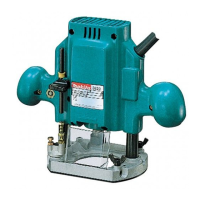
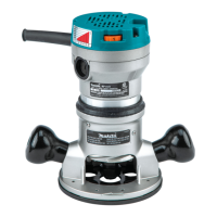
The Makita Router is a power tool designed for various woodworking tasks such as chamfering, grooving, edge cutting, and creating decorative profiles using different types of bits. It is equipped with an electric brake for enhanced safety and control. The tool operates by rotating a bit at high speed to remove material from a workpiece.
Important Technical Specifications:
The manual includes a specifications table detailing key technical aspects of the router:
- Collet chuck capacity: Available in 1/4" (6.35 mm) and 3/8" (9.5 mm) sizes.
- Main body stroke: 35 mm (1-3/8") for the 1/4" collet and 35 mm (1-3/8") for the 3/8" collet.
- No load speed (RPM): 24,000 RPM for both collet sizes.
- Overall length: 211 mm (8-5/16") for both collet sizes.
- Net weight: 2.4 kg (5.3 lbs) for both collet sizes.
The router features "DOUBLE INSULATION," indicating an extra layer of protection against electric shock. The manual also notes that specifications may differ by country.
Usage Features:
The manual provides detailed instructions for various usage aspects:
-
Installing or Removing Router Bit:
- Caution: Always ensure the tool is switched off and unplugged before installing or removing bits.
- Insert the bit all the way into the collet cone and tighten the collet nut securely with two wrenches.
- To remove, reverse the installation procedure.
- Caution: Do not tighten the collet nut without inserting a bit, as this can break the collet cone.
-
Adjusting Depth of Cut:
- Place the tool on a flat surface.
- Loosen the screw securing the stopper pole.
- Loosen the lock lever and lower the tool body until the bit touches the flat surface.
- Tighten the lock lever to secure the tool body.
- Lower the stopper pole until it contacts the adjusting hex bolt. Align the depth pointer with the "O" graduation.
- Raise the stopper pole to the desired depth of cut, indicated on the scale (1 mm or 1/16" per graduation) by the depth pointer.
- Tighten the screw to secure the stopper pole.
- The predetermined depth of cut can then be achieved by loosening the lock lever and lowering the tool body until the stopper pole contacts the adjusting hex bolt.
- Caution: Excessive cutting can overload the motor or make controlling the tool difficult. The depth of cut should not exceed 5/8" for 1/4" diameter bits or 1/4" for 3/4" diameter bits when cutting grooves. For deeper grooves, multiple passes with progressively deeper bit settings are recommended.
-
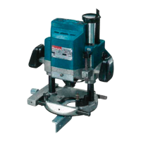
Stopper Block:
- The stopper block has three adjusting hex bolts, each raising or lowering the bit by 0.8 mm (about 1/32") per turn. This allows for three different depths of cut without readjusting the stopper pole.
- To adjust, loosen the hex nuts, turn the hex bolts to the desired position, and then tighten the hex nuts while holding the hex bolts.
- This feature is useful for making three passes with progressively deeper bit settings when cutting deep grooves.
-
Adjusting Lock Lever:
- The locked position of the lock lever is adjustable. Loosen the lock lever 3/4 turn, press its center, and set the hex nut to the desired position before tightening the lock lever.
-
Switch Action:
- Pull the trigger to start the tool and release it to stop.
- Caution: Before plugging in, ensure the trigger switch actuates properly and returns to the "OFF" position when released.
-
Operation:
- Place the tool base on the workpiece without the bit touching it.
- Turn the tool on and wait for the bit to reach full speed.
- Lower the tool body and move it forward over the workpiece, keeping the base flush and advancing smoothly until the cut is complete.
- For edge cutting, the workpiece surface should be on the left side of the bit in the feed direction.
- Note: Moving the tool too fast can result in poor cut quality or damage to the bit/motor. Moving too slowly can burn or mar the cut. The proper feed rate depends on bit size, workpiece type, and depth of cut. It is advisable to make a sample cut on scrap lumber first.
- When using the straight guide, install it on the right side in the feed direction to keep it flush with the workpiece side.
-
Straight Guide (Optional Accessory):
- Used for straight cuts, chamfering, or grooving.
- To install, insert guide bars into the tool base holes, adjust the distance between the bit and guide, and tighten wing bolts.
- When cutting, move the tool with the straight guide flush with the workpiece side.
- If the distance between the workpiece side and cutting position is too wide or the workpiece side is not straight, clamp a straight board to the workpiece and use it as a guide against the router base.
-
Templet Guide (Optional Accessory):
- Provides a sleeve for the bit, allowing use of router with templet patterns.
- To install, loosen screws on the tool base, insert the templet guide, and tighten screws.
- Secure the templet to the workpiece. Place the tool on the templet and move it with the templet guide sliding along the templet side.
Maintenance Features:
- Caution: Always ensure the tool is switched off and unplugged before inspection or maintenance.
- To maintain product safety and reliability, repairs, carbon brush inspection and replacement, and any other maintenance or adjustment should be performed by Makita Authorized or Factory Service Centers, using only Makita replacement parts.
The manual includes a comprehensive list of important safety instructions:
- Keep work area clean and well lit.
- Do not use power tools in damp/wet locations or in the presence of flammable liquids/gases.
- Keep children and visitors away from the work area.
- Store idle tools in a dry, high, or locked-up place out of reach of children.
- Do not force the tool; let it work at its intended rate.
- Use the right tool for the job.
- Dress properly: avoid loose clothing/jewelry, wear rubber gloves and non-skid footwear outdoors, and use protective hair covering.
- Use safety glasses and a face/dust mask in dusty operations.
- Do not abuse the cord: avoid carrying the tool by the cord, yanking it to disconnect, or exposing it to heat, oil, or sharp edges.
- Secure work with clamps or a vise.
- Maintain proper footing and balance.
- Maintain tools with care: keep sharp and clean, follow lubrication/accessory change instructions, inspect cords periodically.
- Disconnect tools when not in use, before servicing, or when changing accessories.
- Remove adjusting keys and wrenches before turning on the tool.
- Avoid unintentional starting; ensure the switch is OFF when plugging in.
- Use outdoor-rated extension cords when working outdoors.
- Stay alert and use common sense; do not operate when tired.
- Check damaged parts before further use; ensure guards and other parts operate properly. Have defective switches replaced.
- Guard against electric shock by preventing body contact with grounded surfaces (e.g., pipes, radiators).
- Use only identical replacement parts for servicing.
- Polarized plugs: This equipment has a polarized plug (one blade wider than the other). If it doesn't fit fully, reverse it. If it still doesn't fit, contact a qualified electrician. Do not alter the plug.
Voltage Warning:
Before connecting the tool to a power source, ensure the voltage matches the tool's nameplate specification. Using a higher voltage can cause serious injury and tool damage. Using a lower voltage is harmful to the motor.
Additional Safety Rules (Specific to Router):
- Handle bits carefully.
- Check bits for cracks or damage before operation; replace immediately if found.
- Avoid cutting nails; remove all nails from the workpiece.
- Hold the tool firmly with both hands.
- Keep hands away from rotating parts.
- Ensure the bit is not contacting the workpiece before turning on the switch.
- Before using on an actual workpiece, let it run to check for vibration or wobbling.
- Be careful of bit rotating direction and feed direction.
- Do not leave the tool running; operate only when hand-held.
- Always switch off and wait for the bit to stop before removing the tool from the workpiece.
- Do not touch the bit immediately after operation as it may be extremely hot.
- Keep the bit retracted when not in use.
Accessories:
The manual lists various accessories and their part numbers, emphasizing that only recommended accessories should be used to avoid injury. These include:
- Templet guides (various sizes)
- Templet guide 25
- Lock nut (for templet guide 25)
- Templet guide adapter (for templet guide 25)
- Straight guide
- Collet cone (1/4")
- Trimmer guide assembly
- Wrenches (22, 13, 8)
- Various bits: Straight (single and 2 flute), Hinge Mortising, Veining (single flute), Round Nose, Core Box, Vee Grooving, 14° Dovetail, Panel Pilot, Corner Rounding, Beading, Cove, 45° Chamfering, Rabbeting, Roman Ogee, Flush Trimmer (self-piloting), 7° Bevel Trimmer (self-piloting), 2 Flute Flush Trimmer, Combination Flush/22° Bevel Trimmer, 3 Flute Flush Trimmer Assembly (self-piloting), 3 Flute 22° Bevel Trimmer Assembly (self-piloting), 3 Flute Flush Replacement Cutter, 3 Flute 22° Bevel Replacement Cutter, 1/4" Replacement Arbor, and Ball Bearing Pilots (various sizes).
Exploded View and Parts List:
An exploded view diagram of the router (Type 1) is provided, along with a corresponding parts list detailing each component's item number, quantity, and description. This includes parts for the machine, armature assembly, and field assembly.
Warranty Policy:
Makita offers a ONE YEAR WARRANTY against defects in workmanship and materials from the date of original purchase. Repairs or replacements are free if the issue is due to defective workmanship or material. The warranty does not cover repairs by unauthorized personnel, normal wear and tear, abuse, misuse, improper maintenance, or alterations. Makita disclaims liability for indirect, incidental, or consequential damages, and implied warranties of merchantability and fitness for a specific purpose are limited to the one-year term. State laws may vary regarding these limitations.