EasyManua.ls Logo

Makita 3621 - User Manual

Makita 3621
16 pages
Print Icon
To Next Page IconTo Next Page
Loading...
INSTRUCTION MANUAL
WARNING:
For your personal safety, READ and UNDERSTAND before using.
SAVE THESE INSTRUCTIONS FOR FUTURE REFERENCE.
www.makitatools.com
Router
MODEL 3621
003251
DOUBLE
INSULATION
Question and Answer IconNeed help?

Do you have a question about the Makita 3621 and is the answer not in the manual?

Summary

SPECIFICATIONS

GENERAL SAFETY RULES

Crucial safety guidelines applicable to all tools for preventing injury.

Work Area Safety

Guidelines for maintaining a safe and clean work environment during tool operation.

Electrical Safety Precautions

Precautions related to the tool's electrical components and power supply.

Personal Safety Guidelines

Operator Awareness and Alertness

Emphasizes operator focus and common sense for safe tool operation.

Appropriate Dress and Personal Items

Guidelines on attire to prevent entanglement with moving parts.

Preventing Accidental Starts

Measures to prevent unintentional tool activation before use.

Tool Control and Balance

Maintaining proper footing, balance, and avoiding overreaching for control.

Mandatory Safety Equipment Use

Mandatory use of eye protection and other safety gear for specific conditions.

Tool Usage and Maintenance

Workpiece Securing Techniques

Proper methods for securing workpieces to prevent instability and loss of control.

Proper Tool Application

Using the correct tool for the application for better and safer results.

Switch Functionality Check

Safety measure against using a tool with a faulty or unresponsive switch.

Power Disconnection Procedure

Procedure for unplugging the tool before adjustments or accessory changes.

Safe Tool Storage

Safe storage practices for tools to prevent unauthorized use.

Tool Maintenance and Care

Importance of keeping tools sharp, clean, and well-maintained for control.

Inspection for Damage

Inspecting for damaged parts or conditions affecting tool operation.

Accessory Compatibility

Caution against using non-manufacturer recommended accessories.

SERVICE AND REPAIR

Qualified Personnel for Service

Requirement for authorized personnel for tool repairs and maintenance.

Use Genuine Replacement Parts

Ensuring safety and reliability by using only genuine Makita replacement parts.

Extension Cord Usage

SPECIFIC SAFETY RULES

Grip Tool by Insulated Surfaces

Safety tip for avoiding shock when cutting near hidden wiring or the cord.

Hearing Protection Requirement

Recommendation for hearing protection during extended periods of operation.

Bit Handling and Inspection

Careful handling and checking bits for damage before operation.

Workpiece Preparation

Instruction to remove nails from workpieces before routing.

Stable Tool Operation

Essential technique for stable and controlled router operation.

Pre-Start Safety Check

Ensuring the bit is clear of the workpiece before starting the tool.

Test Run Procedure

Bit Rotation and Feed Direction

Continuous Operation Rule

Safe Bit Removal

Hot Bit Caution

Power Cord Management

Tool Base Protection

Bit Shank Diameter and Speed

Chemical Material Handling

SYMBOLS EXPLANATION

FUNCTIONAL DESCRIPTION

Depth of Cut Adjustment

Step-by-step guide for setting the desired cutting depth.

Stopper Block Functionality

Explanation of the stopper block's function and adjustments for depth.

Lock Lever Adjustment

Procedure for adjusting the tool's lock lever for stability.

Switch Operation

ASSEMBLY PROCEDURES

Router Bit Installation;Removal

Procedure for securely installing and removing router bits.

Dust Nozzle Attachment

Instructions for attaching the dust nozzle for cleaner operation.

ROUTER OPERATION

Straight Guide Usage

Templet Guide Usage

MAINTENANCE GUIDELINES

ACCESSORIES LIST

FACTORY SERVICE CENTERS

MAKITA LIMITED ONE YEAR WARRANTY

Overview

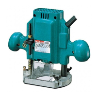
The Makita Router Model 3621 is a power tool designed for various routing applications, offering precision and control for tasks such as chamfering, grooving, and edge cutting. It is a double-insulated tool, which eliminates the need for a three-wire grounded power cord and grounded power supply system, enhancing electrical safety.

Function Description:

The router is primarily used for shaping and cutting wood or similar materials with a rotating bit. Its plunge mechanism allows for controlled depth of cut, making it versatile for different routing operations. The tool is designed to be hand-held during operation, and its base can be set on the workpiece to ensure stability and smooth advancement.

Important Technical Specifications:

  • Model: 3621
  • Collet capacity: 1/4"
  • Plunge capacity: 35 mm (1-3/8")
  • No load speed (RPM): 29,000/min.
  • Overall length: 211 mm (8-5/16")
  • Net weight: 2.4 kg (5.3 lbs)
  • Electrical: 120 V (for US market, as indicated by the extension cord table)
  • Insulation: Double Insulation (Class II Construction)

Usage Features:

Adjusting the Depth of Cut:

The depth of cut is a crucial setting for precise routing. To adjust it:

  1. Place the tool on a flat surface.
  2. Loosen the screw securing the stopper pole.
  3. Loosen the lock lever and lower the tool body until the bit just touches the flat surface.
  4. Tighten the lock lever to lock the tool body in this position.
  5. Lower the stopper pole until it contacts the adjusting hex bolt.
  6. Align the depth pointer with the "0" graduation on the scale.
  7. Raise the stopper pole to the desired depth of cut, indicated by the depth pointer on the scale (1 mm or 1/16" per graduation).
  8. Tighten the screw to secure the stopper pole.
  9. During operation, loosen the lock lever and lower the tool body until the stopper pole contacts the adjusting hex bolt to achieve the predetermined depth.

Important Considerations for Depth of Cut:

  • Excessive cutting depth can overload the motor or make the tool difficult to control.
  • For cutting grooves with an 8 mm (5/16") diameter bit, the depth of cut should not exceed 15 mm (9/16") per pass.
  • For cutting grooves with a 20 mm (13/16") diameter bit, the depth of cut should not exceed 5 mm (3/16") per pass.
  • For deeper grooves, it is recommended to make several passes with progressively deeper bit settings.

Stopper Block:

The stopper block features three adjusting hex bolts, each capable of raising or lowering the tool by 0.8 mm (approximately 1/32") per turn. This allows for obtaining three different depths of cut without readjusting the stopper pole.

  1. Adjust the lowest hex bolt for the deepest cut, following the "Adjusting depth of cut" method.
  2. Adjust the other two hex bolts for shallower depths. The height differences between these bolts correspond to the differences in cut depths.
  3. To adjust the hex bolts, loosen their hex nuts with a wrench, turn the hex bolts to the desired position, and then tighten the hex nuts while holding the hex bolts in place. The stopper block is useful for making three passes with progressively deeper bit settings when cutting deep grooves.

Special Adjustment for Long Bits:

When using a bit with a total length of 60 mm (2-3/8") or more, or an edge length of 35 mm (1-3/8") or more, the standard depth adjustment method may not apply. In such cases:

  1. Loosen the lock lever.
  2. Carefully adjust the bit protrusion below the tool base to the desired depth of cut by moving the tool body up or down.
  3. Re-tighten the lock lever to lock the tool body at that depth of cut.
  4. Keep the tool body locked in this position during use.
  • Caution: Since the bit will always protrude from the tool base in this configuration, exercise extra care when handling the tool.

Adjusting the Lock Lever:

The locked position of the lock lever is adjustable. To adjust it:

  1. Loosen the lock lever by 3/4 turn.
  2. Press the center of the lock lever to release the hex nut.
  3. Set the hex nut to the desired position.
  4. Tighten the lock lever.

Switch Action:

The tool is started by pulling the switch trigger and stopped by releasing it.

  • Caution: Always ensure the switch trigger actuates properly and returns to the "OFF" position when released before plugging in the tool.

Installing or Removing Router Bit:

  1. Insert the bit all the way into the collet cone.
  2. Tighten the collet nut securely with the two wrenches.
  3. To remove the bit, reverse the installation procedure.
  • Caution: Do not tighten the collet nut without inserting a bit, as this can break the collet cone.

Dust Nozzle (Optional Accessory):

For clean cutting operations, a dust nozzle can be installed.

  1. Install the dust nozzle on the router base using the two screws.
  2. Connect a vacuum cleaner to the dust nozzle.

Operation:

  1. Place the tool base on the workpiece without the bit touching it.
  2. Turn the tool on and wait for the bit to reach full speed.
  3. Lower the tool body and move the tool forward over the workpiece surface.
  4. Keep the tool base flush with the surface and advance smoothly until the cut is complete.
  5. When performing edge cutting, the workpiece surface should be on the left side of the bit in the feed direction.

Notes on Feed Rate:

  • Moving the tool too fast can result in a poor quality cut, or damage to the bit or motor.
  • Moving the tool too slowly can burn and mar the cut.
  • The proper feed rate depends on bit size, workpiece type, and depth of cut.
  • It is advisable to make a sample cut on a piece of scrap lumber to check the cut appearance and dimensions before working on the actual workpiece.

Straight Guide:

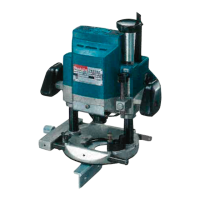
The straight guide is used for straight cuts, such as chamfering or grooving.

  1. Insert the guide bars into the holes in the tool base.
  2. Adjust the distance between the bit and the straight guide.
  3. Tighten the wing bolts to secure the straight guide.
  4. When cutting, move the tool with the straight guide flush with the side of the workpiece.
  5. If the distance between the workpiece side and the cutting position is too wide for the straight guide, or if the workpiece side is not straight, clamp a straight board to the workpiece and use it as a guide against the router base.
  • Note: When using the straight guide, install it on the right side in the feed direction to keep it flush with the workpiece side.

Templet Guide (Optional Accessory):

The templet guide provides a sleeve for the bit, allowing the router to be used with templet patterns.

  1. Loosen the screws on the tool base.
  2. Insert the templet guide.
  3. Tighten the screws.
  4. Secure the templet to the workpiece.
  5. Place the tool on the templet and move it with the templet guide sliding along the side of the templet.

Maintenance Features:

General Maintenance:

  • Always ensure the tool is switched off and unplugged before performing any inspection or maintenance.
  • To maintain product safety and reliability, repairs, carbon brush inspection and replacement, and any other maintenance or adjustment should be performed by Makita Authorized or Factory Service Centers, using only Makita replacement parts.
  • Keep cutting tools sharp and clean. Properly maintained tools with sharp cutting edges are less likely to bind and are easier to control.
  • Check for misalignment or binding of moving parts, breakage, and any other condition that may affect tool operation. If damaged, have the tool serviced before use.
  • Do not smear the tool base with thinner, gasoline, oil, or similar substances, as they may cause cracks.

Cord Care:

  • Do not abuse the cord. Never use it to carry the tool or pull the plug from an outlet.
  • Keep the cord away from heat, oil, sharp edges, or moving parts.
  • Replace damaged cords immediately, as they increase the risk of electric shock.
  • When operating outdoors, use an outdoor extension cord marked "W-A" or "W" to reduce the risk of electric shock.

Storage:

  • Store idle tools out of reach of children and other untrained persons.
  • Straight & groove forming bits

  • Edge forming bits

  • Laminate trimming bits

  • Straight guide

  • Trimmer guide assembly

  • Templet guides

  • Templet guide adapter

  • Lock nut

  • Collet cone 1/4"

  • Dust nozzle

  • Wrench 8

  • Wrench 13

  • Wrench 22

  • Caution: Only use accessories or attachments recommended by the manufacturer for this specific model. Using other accessories may pose a risk of injury. For assistance, contact a local Makita service center.

Makita 3621 Specifications

General IconGeneral
BrandMakita
Model3621
CategoryNetwork Router
LanguageEnglish

Related product manuals