Do you have a question about the Makita 3707FC and is the answer not in the manual?
Guidelines for maintaining a safe working environment, including lighting and clear space.
Precautions related to electrical hazards, tool grounding, and plug compatibility.
Using clamps or other methods to secure the workpiece for stable operation.
Holding the tool by insulated surfaces and checking bits for damage.
Procedure for securely attaching and detaching cutting bits using wrenches.
Procedure for checking and replacing worn carbon brushes for tool longevity.
Information on chemicals in dust and health precautions for California residents.
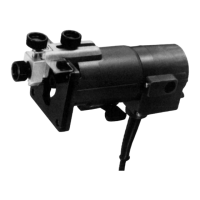
The Makita 3707FC Trimmer is a 1/4" tool designed for various cutting and trimming operations, offering precision and ease of use for both professional and DIY applications.
The trimmer is primarily used for cutting and shaping wood and other materials with a 1/4" collet chuck capacity. It allows for precise adjustment of bit protrusion, enabling users to control the depth of cut. The tool features a switch lever for easy operation, with "I" for ON and "O" for OFF positions. Electronic functions enhance its usability, including constant speed control to maintain consistent rotating speed even under load, which ensures a fine finish. A soft start feature suppresses starting shock, contributing to safety and smoother operation. The trimmer also includes lamps to illuminate the workpiece, improving visibility during use.
To adjust the bit protrusion, the lever is loosened, and the tool base is moved up or down by turning the adjusting roller. Once the desired protrusion is set, the lever is tightened firmly to secure the tool base.
The tool is started by moving the switch lever to the "I" (ON) position and stopped by moving it to the "O" (OFF) position. Users are cautioned to ensure the tool is switched off before plugging it in.
This feature electronically maintains a constant rotating speed, even when the tool is under load, ensuring a consistent and fine finish.
The soft start mechanism suppresses the initial starting shock, providing a safer and smoother start-up.
The lamps are turned on by moving the switch lever to the "ON" side and off by moving it to the "OFF" side. Users are advised not to look directly at the light source.
Bits are inserted all the way into the collet cone, and the collet nut is securely tightened using the two provided wrenches. It is crucial not to tighten the collet nut without a bit inserted to prevent damage to the collet cone. Removal follows the reverse procedure.
The tool base should be placed on the workpiece without the bit making contact. After turning the tool on and allowing the bit to reach full speed, the tool is moved forward over the workpiece surface, keeping the base flush and advancing smoothly until the cut is complete. For edge cutting, the workpiece surface should be on the left side of the bit in the feed direction. Users are advised to avoid moving the tool too fast, which can result in poor cut quality or damage, or too slowly, which can burn or mar the cut. The proper feed rate depends on bit size, workpiece type, and depth of cut. It is recommended to make a sample cut on scrap material first. When using the trimmer shoe, straight guide, or trimmer guide, it should be kept on the right side in the feed direction to ensure it remains flush with the workpiece. For cutting grooves, the depth of cut should not exceed 3 mm (1/8") per pass to prevent motor overload or control difficulty. Deeper grooves require multiple passes with progressively deeper bit settings.
The templet guide provides a sleeve for the bit, allowing the trimmer to be used with templet patterns. To install, the base protector is removed, the templet guide is placed on the base, and the base protector is reinstalled and secured with screws. The templet is then secured to the workpiece, and the tool is moved with the templet guide sliding along its side. It's important to note that the workpiece will be cut slightly differently from the templet due to the distance (X) between the router bit and the outside of the templet guide. This distance can be calculated as: (outside diameter of the templet guide - router bit diameter) / 2.
The straight guide is useful for straight cuts, chamfering, or grooving. It is attached to the guide plate with a bolt, wave washer, flat washer, and wing nut. The straight guide is then attached to the tool with a clamp screw (A). The distance between the bit and the straight guide is adjusted by loosening the wing nut on the straight guide, and then tightened securely. When cutting, the tool is moved with the straight guide flush with the side of the workpiece. If the distance between the workpiece side and the cutting position is too wide, or if the workpiece side is not straight, a straight board can be clamped to the workpiece and used as a guide against the trimmer base.
Circular cuts can be made by assembling the straight guide and guide plate. The minimum radius for circles is 70 mm (2-3/4"), and the maximum is 221 mm (8-11/16"). Circles between 172 mm (6-3/4”) and 186 mm (7-5/16”) in radius cannot be cut using this guide. To perform circular work, align the center hole in the straight guide with the center of the desired circle. Drive a nail (less than 6 mm (1/4") in diameter) into the center hole to secure the straight guide, then pivot the tool clockwise around the nail.
The trimmer guide facilitates trimming and curved cuts in veneers for furniture. Its guide roller rides along the curve, ensuring a fine cut. It is installed on the tool base with clamp screw (A). Clamp screw (B) is loosened to adjust the distance between the bit and the trimmer guide by turning the adjusting screw (1 mm (3/64") per turn). Once adjusted, clamp screw (B) is tightened. During cutting, the tool is moved with the guide roller riding the side of the workpiece.
Always ensure the tool is switched off and unplugged before any adjustments, inspections, or maintenance.
Use a dry cloth to wipe dirt off the lens of the light, being careful not to scratch it, as this may reduce illumination.
Carbon brushes should be regularly removed, checked, and replaced when they wear down to the limit mark. They must be kept clean and free to slip in their holders. Both carbon brushes should be replaced simultaneously with identical carbon brushes. To replace, remove the brush holder caps with a screwdriver, take out the worn brushes, insert new ones, and secure the caps.
For product safety and reliability, all repairs, maintenance, or adjustments should be performed by Makita Authorized or Factory Service Centers, using only Makita replacement parts.
Recommended accessories include:
| Brand | Makita |
|---|---|
| Model | 3707FC |
| Category | Laminate Trimmer |
| Language | English |