Do you have a question about the Makita 9553B and is the answer not in the manual?
Shows symbols used on the tool and their meanings for user understanding.
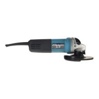
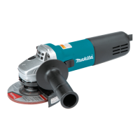
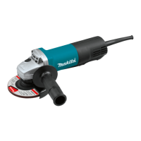
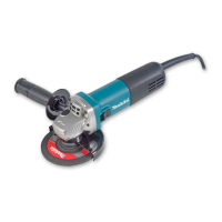
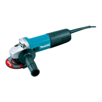
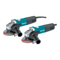
Describes the tool's purpose for grinding, sanding, and cutting metal/stone without water.
Details power connection requirements, voltage, single-phase AC, and double insulation benefits.
Explains how to use the shaft lock to prevent spindle rotation during accessory changes.
Details how to operate the tool's switch lever for starting and stopping.
Instructions for securely installing the side grip (handle) accessory before operation.
Instructions for holding and operating the tool with one hand without a side handle.
This document describes the Makita Angle Grinder models 9553B and 9555B, a double-insulated power tool designed for grinding, sanding, and cutting metal and stone materials without the use of water. It emphasizes safety, proper operation, and maintenance to ensure user safety and tool longevity.
The angle grinder is equipped with a shaft lock mechanism to prevent spindle rotation, facilitating the installation or removal of accessories. To actuate the shaft lock, press it firmly. It is crucial never to actuate the shaft lock while the spindle is moving, as this can damage the tool.
The tool features a switch lever for operation. To start the tool, move the switch lever to the "I" (ON) position. To stop the tool, move the switch lever to the "O" (OFF) position. Always ensure the tool is switched off before plugging it in.
The wheel guard is an essential safety component that must be fitted with its closed side pointing towards the operator. To install, align the protrusion on the wheel guard band with the notch on the bearing box, then rotate the wheel guard approximately 180 degrees and securely tighten the screw. Removal follows the reverse procedure.
For installing or removing depressed center grinding wheels or multi-discs, first mount the inner flange onto the spindle. Then, fit the wheel/disc onto the inner flange and screw the lock nut onto the spindle. To tighten the lock nut, press the shaft lock firmly to prevent spindle revolution, and use the lock nut wrench to securely tighten it clockwise. Removal is the reverse process.
When installing or removing a diamond wheel (an optional accessory), ensure the arrow on the tool points in the same direction as the arrow on the diamond wheel. Mount the inner flange onto the spindle, fit the diamond wheel over the inner flange, and screw the lock nut onto the spindle. Note that the flat side of the lock nut should face the diamond wheel when it is used.
For personal safety, users must read and understand all instructions before using the tool and save them for future reference. Basic safety precautions include keeping the work area clean and well-lit, avoiding damp or wet locations, guarding against electric shock, keeping children away, and storing idle tools safely.
Users should not force the tool; it performs best at its intended rate. Always use the correct tool for the job. Proper attire, including safety glasses, hearing protection, and a dust mask (if the operation is dusty), is recommended. If dust extraction equipment is provided, ensure it is connected and properly used.
The power cord should not be abused; never carry the tool by the cord or yank it from the socket. Keep the cord away from heat, oil, and sharp edges. Secure the workpiece with clamps or a vice for safer operation. Maintain proper footing and balance, and avoid overreaching.
Tools should be maintained with care, keeping cutting tools sharp and clean. Inspect the tool cord and extension cords periodically for damage and have them repaired or replaced by an authorized service facility if necessary. Always remove adjusting keys and wrenches before turning on the tool. Avoid unintentional starting by ensuring the switch is off before plugging in. When using the tool outdoors, use only outdoor extension cords. Stay alert and do not operate the tool when tired.
Before further use, check for damaged parts such as guards or other components to ensure proper operation. Any damaged parts should be repaired or replaced by an authorized service center. Do not use the tool if the switch does not turn it on or off. Only use accessories or attachments recommended in the instruction manual or catalog to avoid personal injury. Repairs should only be carried out by qualified persons using original spare parts.
Additional safety rules include always using eye and ear protection, wearing other personal protective equipment like a dust mask, gloves, helmet, and apron. Always ensure the tool is switched off and unplugged before any work on it. Keep guards in place. Use only wheels with the correct size and a maximum operating speed at least as high as the tool's nameplate. For depressed center wheels, use only fiberglass-reinforced wheels.
Carefully check the wheel for cracks or damage before operation and replace damaged wheels immediately. Observe manufacturer instructions for mounting and use of wheels, and handle/store them with care. Do not use separate reducing bushings or adaptors for large hole abrasive wheels. Use only flanges specified for this tool. Avoid damaging the spindle, flange, or lock nut, as this can cause wheel breakage. For threaded hole wheels, ensure the thread is long enough to accept the spindle length.
Before using the tool on a workpiece, test run it at the highest no-load speed for at least 30 seconds in a safe position. Stop immediately if there is vibration or wobbling, which could indicate poor installation or a poorly balanced wheel, and determine the cause. Ensure the workpiece is properly supported.
Hold the tool firmly and keep hands away from rotating parts. Ensure the wheel is not contacting the workpiece before turning on the switch. Use the specified surface of the wheel for grinding. Do not use cutting-off wheels for side grinding. Watch out for flying sparks and direct them away from yourself and others. Be aware that the wheel continues to rotate after the tool is switched off. Do not touch the workpiece immediately after operation as it may be extremely hot. Position the power cord to always stay behind the machine.
In hot, humid, or dusty conditions, use a short-circuit breaker (30 mA) for safety. Do not use the tool on materials containing asbestos, or with water or grinding lubricant. Keep ventilation openings clear, especially in dusty conditions. If clearing dust is necessary, disconnect the tool from the mains supply and use non-metallic objects to avoid damaging internal parts. When using a cut-off wheel, always work with the dust collecting wheel guard required by domestic regulation. Cutting discs must not be subjected to any lateral pressure.
When operating without a side handle, always hold the tool firmly with one hand on the housing, avoiding contact with metal parts. When operating with a side handle, hold the tool firmly with one hand on the housing and the other on the side handle. Turn the tool on and apply the wheel or disc to the workpiece, generally keeping the edge at about a 15-degree angle to the surface. During the break-in period with a new wheel, avoid working in the "B" direction (which cuts into the workpiece) until the edge is rounded off, after which both "A" and "B" directions can be used.
For operation with a diamond wheel, avoid forcing or exerting excessive pressure, or allowing the wheel to bend, pinch, or twist in the cut, as this can cause overheating of the motor and dangerous kickback. Always replace the wheel if the tool is dropped while grinding. Never bang or hit the grinding disc or wheel onto the work. Avoid bouncing and snagging the wheel, especially when working corners or sharp edges, as this can lead to loss of control and kickback. Never use the tool with wood cutting blades or other sawblades, as these can kick and cause loss of control. After cutting, switch off the tool and wait for the wheel to stop completely before putting it down.
Always ensure the tool is switched off and unplugged before attempting any inspection or maintenance. The tool and its air vents must be kept clean. Regularly clean the tool's air vents or whenever they become obstructed.
To maintain product safety and reliability, all repairs, carbon brush inspection and replacement, and any other maintenance or adjustments should be performed by Makita Authorized Service Centers, using genuine Makita replacement parts.
| Power Input | 710W |
|---|---|
| Wheel Diameter | 100 mm (4") |
| No Load Speed | 11, 000 RPM |
| Voltage | 120 V |
| Spindle Thread | M10 x 1.5 |
| Cable Length | 2.5 m (8.2 ft) |
| Arbor Size | 16mm |
| Amperage | 6.0 A |
| Net Weight | 1.8 kg (4.0 lbs) |