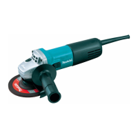
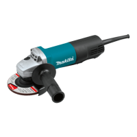
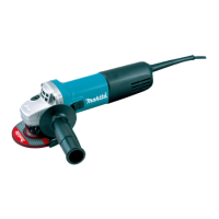
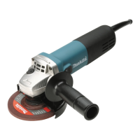
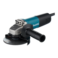
This document is an instruction manual for the Makita Angle Grinder, models 9553NB, 9554NB, and 9555NB. It provides essential information regarding the tool's specifications, safety guidelines, functional description, assembly, operation, and maintenance.
Function Description
The Makita Angle Grinder is designed for grinding, sanding, and cutting metal and stone materials without the use of water. It features a shaft lock mechanism to prevent spindle rotation during accessory installation or removal, and a slide switch for operation. The tool is double-insulated, making it suitable for use with sockets without an earth wire.
Important Technical Specifications
The manual details the specifications for three models: 9553NB, 9554NB, and 9555NB.
| Model |
Depressed center wheel diameter |
Spindle thread |
No load speed (min⁻¹) |
Overall length |
Net weight |
Safety class |
| 9553NB |
100 mm |
M10 |
11,000 |
258 mm |
1.4 kg |
Ⅱ |
| 9554NB |
115 mm |
M14 |
10,000 |
258 mm |
1.4 kg |
Ⅱ |
| 9555NB |
125 mm |
M14 |
10,000 |
258 mm |
1.4 kg |
Ⅱ |
The typical A-weighted sound pressure level is 84 dB (A), and the noise level under working conditions may exceed 85 dB (A). The typical weighted root mean square acceleration value is not more than 2.5 m/s². These values are obtained according to EN50144.
Usage Features
- Shaft Lock: The shaft lock is used to prevent spindle rotation when installing or removing accessories. It should never be actuated when the spindle is moving to prevent damage to the tool.
- Switch Action: The tool is started by sliding the slide switch towards the "I (ON)" position. For continuous operation, the front of the slide switch can be pressed to lock it. To stop the tool, the rear of the slide switch is pressed, then slid towards the "O (OFF)" position. Users are advised to always check that the slide switch actuates properly and returns to the "OFF" position when depressed before plugging in the tool.
- Side Grip (Handle) Installation: The side grip should be securely screwed onto the tool before operation.
- Wheel Guard Installation/Removal: The wheel guard must be fitted so that its closed side points towards the operator. It is mounted by aligning the protrusion on the wheel guard band with the notch on the bearing box, then rotated approximately 180 degrees and secured by tightening a screw.
- Depressed Center Grinding Wheel/Multi-disc Installation/Removal: The inner flange is mounted onto the spindle, followed by the wheel/disc, and then the lock nut is screwed onto the spindle. To tighten the lock nut, the shaft lock is pressed firmly to prevent spindle revolution, and a lock nut wrench is used to tighten clockwise. The shaft lock should only be actuated when the spindle is not moving.
- Grinding and Sanding Operation: The tool should be held firmly with one hand on the housing and the other on the side handle. The wheel or disc should be applied to the workpiece after turning the tool on. Generally, the edge of the wheel or disc should be kept at an angle of about 15 degrees to the workpiece surface. During the break-in period with a new wheel, the grinder should not be worked in the "B" direction as it may cut into the workpiece. Once the wheel's edge is rounded off, it can be worked in both "A" and "B" directions.
- Safety Precautions: The manual emphasizes numerous safety rules, including keeping the work area clean, considering the work area environment, guarding against electric shock, keeping children away, storing idle tools safely, using the right tool for the job, dressing properly, using safety glasses and hearing protection, connecting dust extraction equipment, not abusing the cord, securing the workpiece, not overreaching, maintaining tools with care, disconnecting tools when not in use or servicing, removing adjusting keys and wrenches before starting, avoiding unintentional starting, using outdoor extension leads, staying alert, checking damaged parts, and having the tool repaired by qualified personnel.
- Additional Safety Rules: Specific to angle grinders, users are advised to always use eye and ear protection, wear other personal protective equipment, ensure the tool is switched off and unplugged before any work, keep guards in place, use only wheels with correct size and maximum operating speed, check wheels for cracks or damage, observe manufacturer instructions for wheel mounting, handle and store wheels with care, not use separate reducing bushings or adaptors, use only specified flanges, not damage the spindle, flange, or lock nut, ensure threaded hole wheels have sufficient thread length, test run the tool at highest no load speed for 30 seconds in a safe position, properly support the workpiece, hold the tool firmly, keep hands away from rotating parts, ensure the wheel is not contacting the workpiece before switching on, use the specified surface for grinding, not use cutting off wheels for side grinding, watch out for flying sparks, pay attention to wheel rotation after switch-off, not touch hot workpieces, position the power cord behind the machine, use a short-circuit breaker in hot/humid/dusty conditions, not use on asbestos-containing materials, not use water or grinding lubricant, keep ventilation openings clear, and not subject cutting discs to lateral pressure.
Maintenance Features
- Cleaning: The tool and its air vents must be kept clean. Regular cleaning of the air vents is necessary, or whenever they become obstructed. If it becomes necessary to clear dust, the tool should first be disconnected from the mains supply, and non-metallic objects should be used to avoid damaging internal parts.
- Repairs and Parts: To maintain product safety and reliability, repairs, carbon brush inspection and replacement, and any other maintenance or adjustment should be performed by Makita Authorized Service Centers, using genuine Makita replacement parts.
- Inspection: Users are advised to always ensure the tool is switched off and unplugged before attempting any inspection or maintenance.