9 ENGLISH
Function Status Status of the LED indicator/beeper Action to be taken
LED indicator Beeper
Motor failure Motor failure has been
detected. At this time,
tool does not work.
Flickers in red and green
alternatively.
A series of short beeps Ask your local Makita
Service Center for repair.
Double-hitting detection This function works
when a screw is refas-
tened after fastening.
Lights up in red. A long beep –
Maintenance alarm This function shows the
maintenance time has
come according to your
preset number of screws
driven.
Flickers in yellow. – Reset the alarm with the
application software.
Tool in connection with
PC (no data communica-
tion started/communica-
tion unavailable)
This function shows data
cannot be exchanged
between the tool and
PC in spite of the
connection.
Flickers in yellow. – Restart the application
software and re-connect
the USB cable.
Tool in connection with
PC (data communication
started)
This function shows
the tool is connected to
PC and data exchange
between the tool and PC
can be done in normal
conditions.
Flickers in green. – –
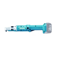
Adjusting the fastening torque
1
2
3
►1. Screw 2. Ring 3. Clutch case
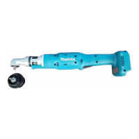
1
3
2
►1. Scale 2. Hole for adjusting grip 3. Yellow line
When you wish to drive machine screws, wood screws,
hex bolts, etc. with the predetermined torque, adjust the
fastening torque as follows.
1. First remove the battery cartridge from the tool.
2. Remove the protector from the clutch case.
3. Loosen and remove the screw that secures ring.
4. Rotate the ring on the tool by hand so that a hole
can be seen below the ring.
5. Place the battery cartridge in place and pull the
switch trigger. Release it so that the adjusting ring
rotates and the hole becomes visible as illustrated.
And then remove the battery cartridge.
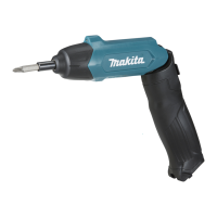
1
►1. Adjusting grip
6. Use an optional adjusting grip to adjust the fasten-
ing torque. Insert the pin of the adjusting grip into
the hole on the tool. And then, turn the adjusting
grip clockwise to set a greater fastening torque,
and counterclockwise to set a smaller fastening
torque.
7. Align the edge of the adjusting ring with your
desired number on the fastening torque scale.
8. Insert the battery cartridge and be sure that a fas-
tening torque has been set up by using a fastening
torque tester.
9. Rotate the ring on the tool and then tighten the
screw to secure the ring.
10. Attach the protector back to the clutch case.
NOTE:
• Numbers on the fastening torque scale is a
guideline to set up your desired fastening
torque.

 Loading...