Do you have a question about the Makita Makstar BDF452 and is the answer not in the manual?
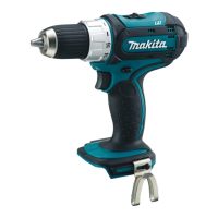
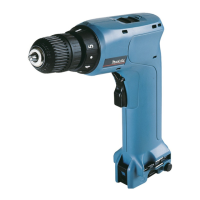
Details the development of the 18V cordless driver, highlighting its compact design, 4-pole motor, lithium-ion battery, and ergonomic grip.
Lists the different model numbers, battery types, chargers, housing colors, and target countries for product availability.
Provides detailed specifications including voltage, battery capacity, maximum output, no-load speed, drill chuck capacity, torque settings, and net weight.
Lists the accessories that are supplied as standard with the tool, such as bits and carrying cases.
Lists optional accessories that can be purchased separately, including various chargers and drill bits.
Lists the essential tools needed for performing repair and maintenance tasks on the tool.
Notes that the gear section is factory-lubricated and does not require additional lubrication during repair.
Provides step-by-step instructions for removing and reinstalling the drill chuck, including necessary precautions.
Details the procedure for disassembling the gear assembly from the motor section and housing.
Explains how to separate the motor section from the gear assembly and remove the yoke unit.
Guides on correctly assembling the motor section, including yoke unit orientation and armature insertion.
Instructions for connecting the gear assembly, pinion gear, armature, and speed change lever assembly.
Steps for assembling the yoke unit into the housing, fitting the change ring, and attaching the F/R change lever.
Details on how to attach the F/R change lever to the switch and the brush holder assembly to the housing.
Instructions for assembling Housing R to Housing L and correctly installing the carbon brushes.
Procedure for mounting the rear cover after all internal components have been assembled.
Diagram illustrating the electrical layout, including the switch, FET, LED, motor terminals, and brush holder.
Diagram showing the routing of LED job light wires and switch wires, including wire holder placements and terminal connections.
| Type | Cordless Drill |
|---|---|
| Voltage | 18V |
| Battery Type | Li-ion |
| Chuck Capacity | 1.5 - 13 mm |
| Max Torque | 42 Nm |
| Max. in steel | 13 mm |
| Torque Settings | 16 |
| Max. Fastening Torque (Hard) | 42 Nm |
| Chuck Size | 13 mm |
| No Load Speed (Hi) | 1700 RPM |
| No Load Speed (Lo) | 400 RPM |