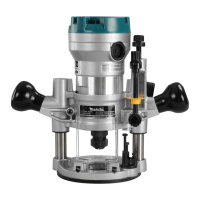
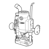
This document describes the Makita Router models RP1100 and RP1101, providing instructions for their safe operation, functional features, and maintenance.
General Safety Rules
The manual emphasizes the importance of reading and understanding all instructions to prevent electric shock, fire, and serious personal injury. Key safety guidelines include:
- Work Area Safety: Keep the work area clean, well-lit, and free from clutter. Avoid operating power tools in explosive atmospheres or in the presence of flammable materials. Keep bystanders, children, and visitors away to prevent distractions.
- Electrical Safety: Grounded tools must be plugged into a properly installed and grounded outlet. Never remove the grounding prong or modify the plug. Do not use adapter plugs. If the tool malfunctions, grounding provides a low-resistance path for electricity. Avoid body contact with grounded surfaces like pipes, radiators, ranges, and refrigerators. Do not expose power tools to rain or wet conditions. Do not abuse the cord; keep it away from heat, oil, sharp edges, or moving parts, and replace damaged cords immediately. When operating outdoors, use an outdoor extension cord marked "W-A" or "W".
- Personal Safety: Stay alert, watch what you are doing, and use common sense. Do not operate the tool while tired or under the influence of drugs, alcohol, or medication. Dress properly, avoiding loose clothing, jewelry, or long hair that could get caught in moving parts. Ensure the switch is off before plugging in to prevent accidental starting. Remove adjusting keys or wrenches before turning the tool on. Maintain proper footing and balance, and use safety equipment such as eye protection, dust masks, non-skid safety shoes, hard hats, or hearing protection as appropriate.
- Tool Use and Care: Use clamps or other practical means to secure the workpiece. Do not force the tool; use the correct tool for the application. Do not use the tool if the switch does not turn it on or off. Disconnect the plug from the power source before making adjustments, changing accessories, or storing the tool. Store idle tools out of reach of children. Maintain tools with care, keeping cutting tools sharp and clean. Check for misalignment, binding, breakage, or any other condition that may affect operation. Use only accessories recommended by the manufacturer.
Specific Safety Rules for Routers
Additional safety rules specific to routers are provided:
- Hold the tool by insulated gripping surfaces when performing operations where the cutting tool may contact hidden wiring or its own cord.
- Wear hearing protection during extended periods of operation.
- Handle bits very carefully.
- Check bits for cracks or damage before operation and replace immediately if found.
- Avoid cutting nails; inspect and remove all nails from the workpiece.
- Hold the tool firmly with both hands.
- Keep hands away from rotating parts.
- Ensure the bit is not contacting the workpiece before turning the switch on.
- Before using on an actual workpiece, let it run for a while to check for vibration or wobbling.
- Be careful of the bit rotating direction and the feed direction.
- Do not leave the tool running; operate it only when hand-held.
- Always switch off and wait for the bit to come to a complete stop before removing the tool from the workpiece.
- Do not touch the bit immediately after operation as it will be extremely hot.
- Always lead the power supply cord away from the tool towards the rear.
- Do not smear the tool base with thinner, gasoline, oil, or similar substances, as they may cause cracks.
- Use cutters of the correct shank diameter suitable for the tool's speed.
- Be cautious of materials containing toxic chemicals; prevent dust inhalation and skin contact, and follow material supplier safety data.
Functional Description
The router features several components for adjusting and controlling its operation:
- Adjusting the Depth of Cut: To set the depth of cut, place the tool on a flat surface, press the lock lever, and lower the tool body until the bit touches the surface. Release the lock lever. Loosen the stopper pole setting nut counterclockwise. While pressing the fast-feed button, lower the stopper pole until it contacts the adjusting hex bolt. Align the depth pointer with the "0" graduation on the scale. To achieve the desired depth, press the fast-feed button and raise the stopper pole. Minute adjustments (1.6 mm or 1/16" per turn) can be made by turning the adjusting knob. Once the depth is set, tighten the stopper pole setting nut clockwise. The predetermined depth of cut is achieved by pressing the lock lever and lowering the tool body until the stopper pole contacts the adjusting hex bolt of the stopper block.
- Caution: Excessive cutting (more than 15 mm or 9/16" with an 8 mm or 5/16" diameter bit, or more than 5 mm or 3/16" with a 20 mm or 13/16" diameter bit) can overload the motor or make the tool difficult to control. For deep grooves, make multiple passes with progressively deeper bit settings.
- Nylon Nut: The nylon nut adjusts the upper limit of the tool body. If the bit tip is retracted more than required from the base plate surface, turn the nylon nut to lower the upper limit.
- Caution: Do not lower the nylon nut too far, as the bit could protrude dangerously.
- Stopper Block: The stopper block has three adjusting hex bolts that raise or lower by 0.8 mm (1/32") per turn, allowing for three different depths of cut without readjusting the stopper pole. To adjust, loosen the hex nuts on the hex bolts with a wrench, then turn the hex bolts to the desired position, and re-tighten the hex nuts while holding the hex bolts. This feature is useful for making multiple passes with progressively deeper bit settings when cutting deep grooves.
- Switch Action: The tool is started by moving the switch lever to the "I" (ON) position and stopped by moving it to the "O" (OFF) position. The switch can be locked in the "ON" position for extended use, but caution and a firm grasp on the tool are advised.
- Caution: Always check that the tool is switched off before plugging it in.
- Speed Adjusting Dial (RP1101 only): This dial allows the user to change the tool speed from settings 1 to 6. Higher numbers correspond to higher speeds (up to 24,000 RPM at setting 6), and lower numbers to lower speeds (down to 8,000 RPM at setting 1). This enables selecting the ideal speed for different materials and bit diameters.
- Caution: Continuous operation at low speeds can overload the motor. The dial should not be forced past settings 1 or 6, as this may damage the speed adjusting function.
Assembly and Operation
- Installing or Removing the Bit: Insert the bit all the way into the collet chuck, then withdraw it slightly (approx. 2mm or 1/16"). Securely tighten the collet chuck with two wrenches. These routers accommodate 1/2" diameter shank bits. For 1/4" diameter shank bits, replace the equipped collet chuck with the provided 1/4" accessory. To remove, reverse the installation procedure.
- Caution: Always use a collet suitable for the bit's shank diameter. Do not tighten the collet chuck without a bit inserted, as this can break the chuck. When using bits larger than 1-1/4" in diameter, install a base plate with a 2-1/2" center hole.
- Operation: Place the tool base on the workpiece without the bit touching. Turn the tool on and wait for the bit to reach full speed. Lower the tool body by pressing the lock lever, then release the lock lever at the lowest position and push it further to lock the tool body securely. Move the tool forward smoothly over the workpiece surface until the cut is complete. For edge cutting, the workpiece surface should be on the left side of the bit in the feed direction.
- Note: Ensure the tool raises automatically when the lock lever is loosened, and the bit position is higher than the tool base when not operating. Moving the tool too fast can result in poor cut quality or damage to the bit/motor. Moving it too slowly can burn and mar the cut. The proper feed rate depends on bit size, workpiece type, and depth of cut. It is advisable to make a sample cut on scrap lumber first.
- Straight Guide (Optional Accessory): The straight guide is used for straight cuts, chamfering, or grooving. Insert the guide bars into the holes in the tool base, adjust the distance between the bit and the guide, and tighten the hex socket bolts. When cutting, move the tool with the straight guide flush against the workpiece side. If the workpiece side is too far or not straight, clamp a straight board to the workpiece and use it as a guide against the base.
- Note: When using the straight guide, install it on the right side in the feed direction to keep it flush with the workpiece.
- Templet Guide (Optional Accessory): The templet guide provides a sleeve for the bit, allowing the tool to be used with templet patterns. To install, insert the templet guide into the center hole of the base plate and secure it with the lock nut. Secure the templet to the workpiece, place the tool on the templet, and move the tool with the templet guide sliding along the templet's side.
Maintenance
- Caution: Always ensure the tool is switched off and unplugged before performing any inspection or maintenance.
- Replacing Carbon Brushes: Regularly remove and check the carbon brushes. Replace them when they wear down to the limit mark. Keep the carbon brushes clean and ensure they slip freely in their holders. Both carbon brushes should be replaced simultaneously with identical carbon brushes. To replace, use a screwdriver to remove the brush holder caps, take out the worn brushes, insert new ones, and secure the caps.
- For product safety and reliability, all repairs, maintenance, or adjustments should be performed by Makita Authorized or Factory Service Centers using Makita replacement parts.
Accessories
Recommended accessories include:
- Straight & groove forming bits
- Edge forming bits
- Laminate trimming bits
- Straight guide
- Templet guides
- Lock nut
- Clear base plate (Center hole 2-1/2")
- Wrench 8
- Wrench 27
- Dust nozzle
The manual concludes with a warning about dust created by power sanding, sawing, grinding, drilling, and other construction activities, which may contain chemicals known to cause cancer, birth defects, or other reproductive harm according to California Proposition 65. It advises working in well-ventilated areas and using approved safety equipment like dust masks. A Makita Limited One Year Warranty is also provided, covering defects in workmanship and materials, with specific exclusions and disclaimers.