6
the blades.
1
2
3
4
5
6
7
8
9
10
011927
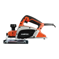
2. To install the blades, loosely attach the adjusting
plate to the set plate with the screws and set the
mini planer blade on the gauge base so that the
cutting edge of the blade is perfectly flush with the
inside flank of the gauge plate.
3. Set the adjusting plate/set plate on the gauge base
so that the planer blade locating lugs on the set
plate rest in the mini planer blade groove, then
press in the heel of the adjusting plate flush with
the back side of the gauge base and tighten the
screws.
4. It is important that the blade sits flush with the
inside flank of the gauge plate, the planer blade
locating lugs sit in the blade groove and the heel of
the adjusting plate is flush with the back side of the
gauge base. Check this alignment carefully to
ensure uniform cutting.
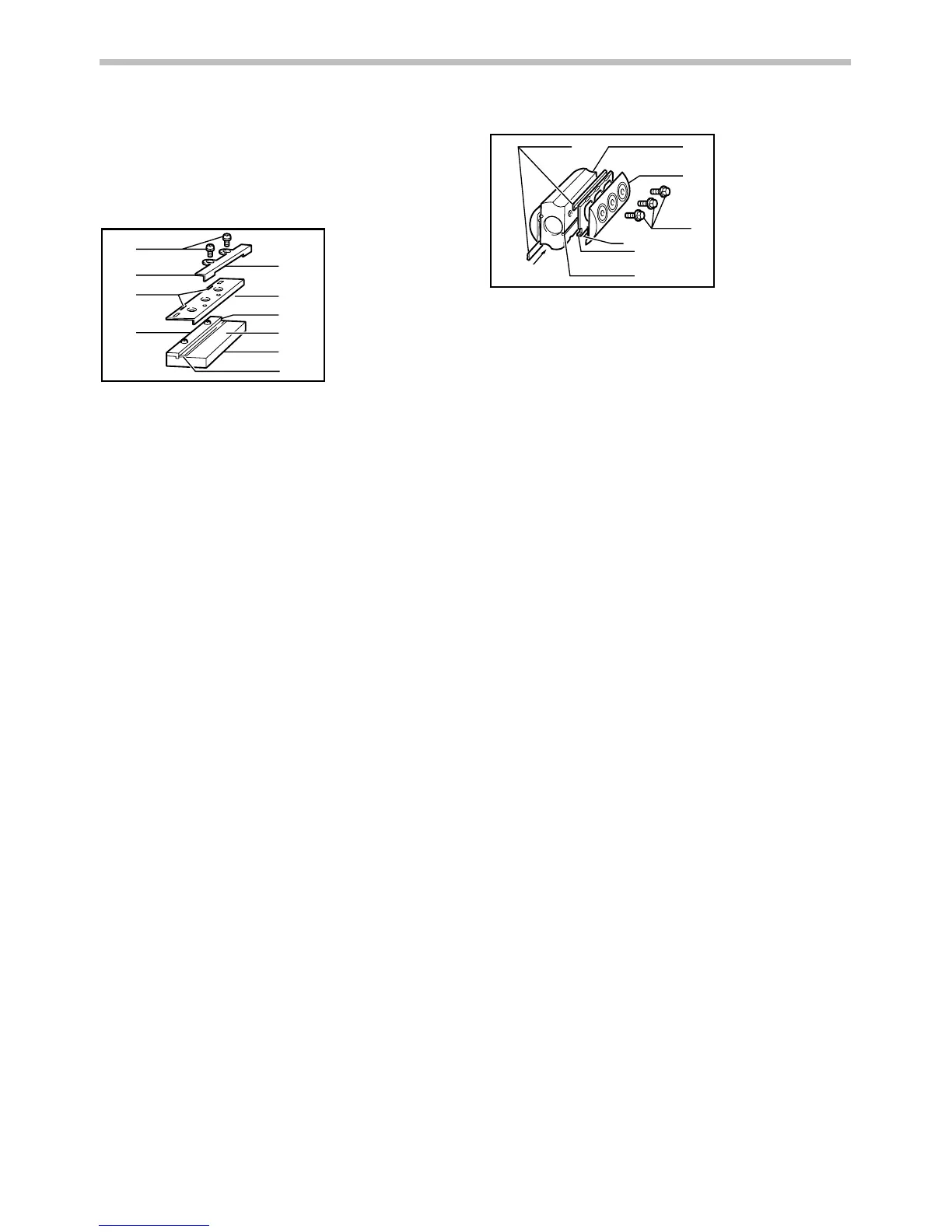
5. Slip the heel of the adjusting plate into the groove
of the drum.
1
2
3
4
5
6
7
011928
6. Set the drum cover over the adjusting plate/set
plate and screw in the three bolts so that a gap
exists between the drum and the set plate to slide
the mini planer blade into position. The blade will
be positioned by the planer blade locating lugs on
the set plate.
7. The blade's lengthwise adjustment will need to be
manually positioned so that the blade ends are
clear and equidistant from the housing on one side
and the metal bracket on the other.
8.
Tighten the three bolts (with the socket wrench
provided) and rotate the drum to check
clearances between the blade ends and the tool
body.
9. Check the three bolts for final tightness.
10. Repeat procedures 1 - 9 for the other blade.
For the correct planer blade setting
Your planing surface will end up rough and uneven,
unless the blade is set properly and securely. The blade
must be mounted so that the cutting edge is absolutely
level, that is, parallel to the surface of the rear base.
Refer to some examples below for proper and improper
settings.
1. Mini planer blade
2. Groove
3. Set plate
4. Bolts
5. Drum cover
6. Drum
7. Adjusting plate
1. Screws
2. Adjusting plate
3. Planer blade
locating lugs
4. Gauge plate
5. Heel of
adjusting plate
6. Set plate
7. Inside flank of
gauge plate
8. Gauge base
9. Back side of
gauge base
10.
Mini planer blade
 Loading...