INSTALLATION AND ELECTRICAL WIRING PROCEDURE
PN 605/UNILITE
®
MODULE: Apply a thin coat of silicone grease to the
bottom of the module before mounting the module to its plate in the dis-
tributor.
PN 609 and PN 605: Slide the three wires from the MODULE, through
the grommet, to outside the distributor housing. Put the three wires from
the MODULE in the TERMINAL PIN HOUSING: GREEN WIRE in hole
#1, BROWN WIRE in hole #2, RED WIRE in hole #3. Plug the three wire
harness (PN 29349, not supplied with this kit) into the TERMINAL PIN
HOUSING.
WARNING: Make sure that the vehicle is originally equipped from
the factory with an ignition ballast resistor or loom resistance wire
from the ignition switch to the coil (+) terminal. If the vehicle is not
originally equipped from the factory with an ignition ballast resistor
or loom resistance wire, a Mallory ballast resistor, PN 700, must be
installed in series on the wire from the ignition switch to the coil (+)
terminal. See a service manual for the vehicle for further information.
For example, vehicles equipped with Ford TFI, or Delco HEI ignition
require the installation of a Mallory ballast resistor, PN 700. Failure to
use a resistor will result in the eventual destruction of the module.
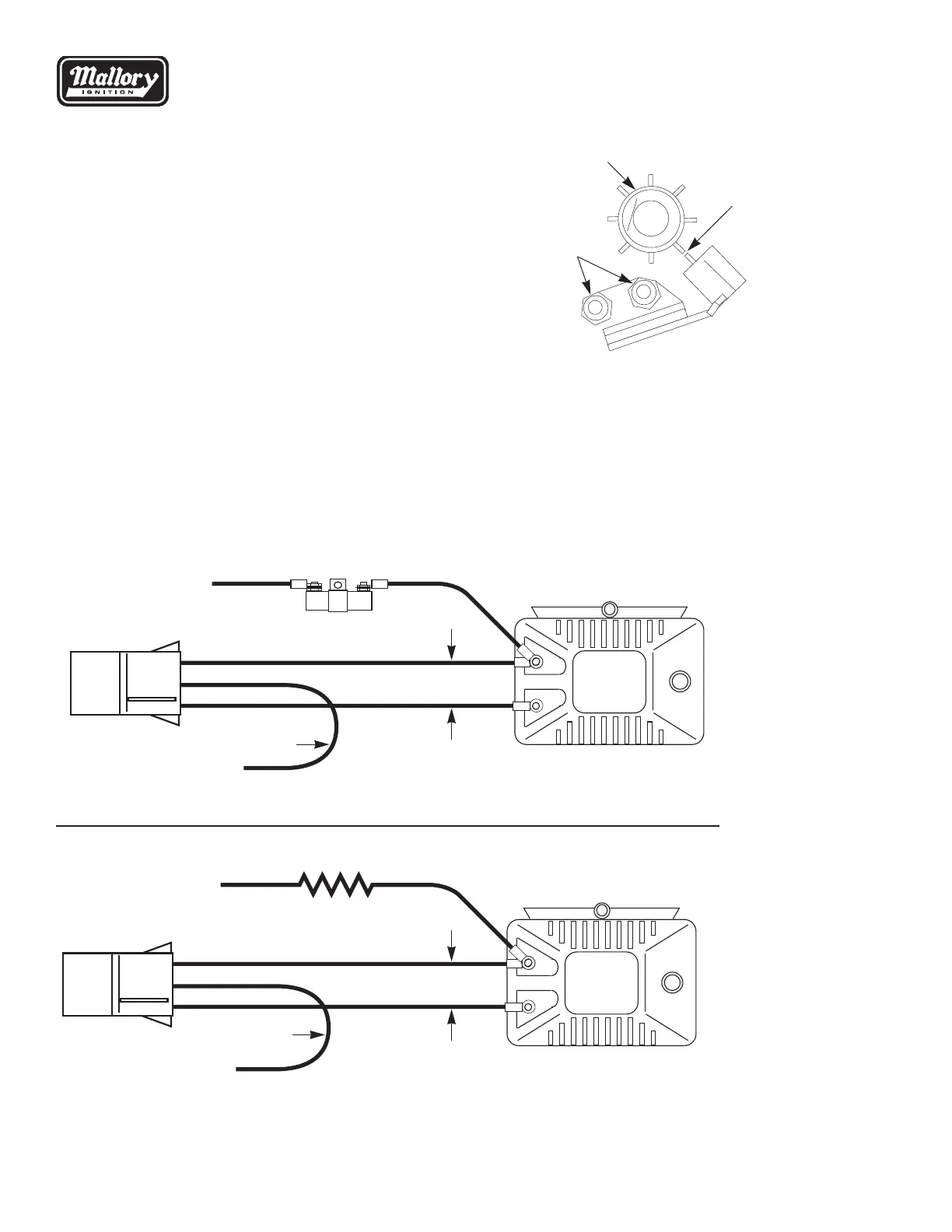
IGNITION MODULE PN 605 and PN 609
Reluctor
Set gap (between .007" – .010")
when a tooth on the reluctor is
pointing directly at the center of
the metal pole on the magnetic
pickup. Tighten the magnetic
pickup mounting nuts.
To set pickup gap:
Loosen the two magnetic
pickup mounting nuts.
A .0075" polyester gauge is provided to assist in setting the pickup gap.
Connect the three wires as follows:
If a HYFIRE
®
or other aftermarket ignition control is being used, connect
the MODULE according to the instructions supplied with the HYFIRE
®
or
aftermarket ignition control.
RED WIRE: Power/voltage for the MODULE. Connect to coil (+) terminal.
GREEN WIRE: Ignition trigger. Connect to coil (–) terminal.
BROWN WIRE: Ground for the MODULE. Connect to ENGINE BLOCK
GROUND. Clean away any grease, oil, and paint from the
mounting surface before the connection is made.
+12V FROM IGNITION SWITCH
GROUND TO ENGINE BLOCK
IGNITION BALLAST RESISTOR RED
GREENBROWN
+12V FROM IGNITION SWITCH
GROUND TO ENGINE BLOCK
LOOM RESISTANCE WIRE
RED
GREEN
BROWN
NOTE—
When using a HYFIRE
®
or
other aftermarket ignition
control, connect the MODULE
according to the instructions
supplied with the HYFIRE
®
or
aftermarket ignition control.
NOTE—
If your vehicle is difficult to
start, remove the red wire
from the plus (+) side of the
ignition coil and connect it
to the ignition switch side of
the ballast resistor.