V
A
V
B
IMPACT
REBOUND
TIME
VELOCITIES
2.2 Leeb Hardness Testing Principle
An impact body with a spherical test tip made of tungsten carbide is
propelled against the sample surface by a spring force and then
rebounds back. At a distance of 1mm from the sample surface, the
impact and rebound velocity of the impact body are measured by the
following method: A permanent magnet embedded in the impact body,
when passing through the coil in its coil holder, induces in the coil an
electric voltage proportional to the velocities of the magnet. Leeb
hardness is expressed by the following formula:
HL=1000×(V /V )
B A
Where: HL is Leeb Hardness
V is the rebound velocity of the impact body
B
V is the impact velocity of the impact body
A
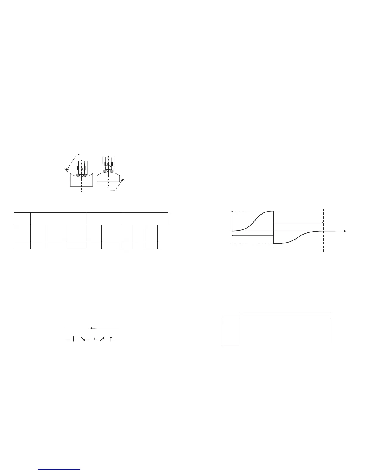
The voltage characteristic of output signal, when the impact body
passes through the induction coil is illustrated in the following figure:
Voltage Characteristic of output signal
A Leeb’s Hardness Tester measures the hardness of sample material in
terms of Hardness Leeb (HL), which can be converted into other
Hardness units (Rockwell B and C, Vicker, Brinell and Shore D).
When measuring the hardness of a sample material using the traditional
static hardness testing method, a change of applied pressure will result
in a change in the hardness reading. This will also happen during a
Leeb’s Hardness test when you change the impact device. In measuring
the hardness of the same test sample with different impact devices, the
Leeb’s hardness values obtained will vary.
For Example: 760 HLD≠760HLC≠760HLG
2.3 Symbols and illustrations of hardness scale
Fig 2.4
Symbols
Illustrations
Leeb hardness value used with impact device D
Brinell hardness value
Rockwell B hardness value
Rockwell C hardness value
Shore hardness value
Vicker hardness value
LD
HB
HRB
HRC
HSD
HV
4
R
R
3.5 Samples with Curved Surfaces
The larger the curvature of the workpiece’s surface, the easier the
testing operation. Under normal conditions, testing can be done directly
with the standard support ring to a curvature with radius of 1 3/16”
(30mm) or longer.
For a workpiece with a radius of less than 1 3/16” (30mm), a special
support ring should be used for testing.
For impact device type D , R =30mm
min
3.6 Test Sample Properties
Table 3.1
4 Operation of the tester
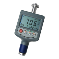
4.1 Power on/off
* Press the POWER/MENU key, now power is on. The instrument is in
working mode.
* The LCD will display the same settings that were previously set. If the
display meets your current testing requirements, you can start the test
immediately. If not, you can enter your required settings using the
keypad.
* The tester can be turned off by pressing the POWER/MENU key for 3
seconds while OFF shows on the display.
4.2 Setting your Impact Direction
Use the DIR/SHIFT button to move the cursor until you reach the desired
direction.
Press DIR/SHIFT key
Sample
Impact
Device
D
Needs
Support
Needs to
be
stabilized
No stren-
gthening
needed
Sample Weight
(kg)
Min. Thickness
(mm)
Sample
Hardened
layer
ISO Ra Rz
Max. Roughness
(or Min. Fineness)
0.05-2 2.5 >5 3 0.8
N7
2µm 10µm
∇6
7
Fig 3.2
Fig 3.2
 Loading...