7
S
15°-30°
15°-30°
T
T
V
S
E
Z
NO
YES
W
X
F
Z
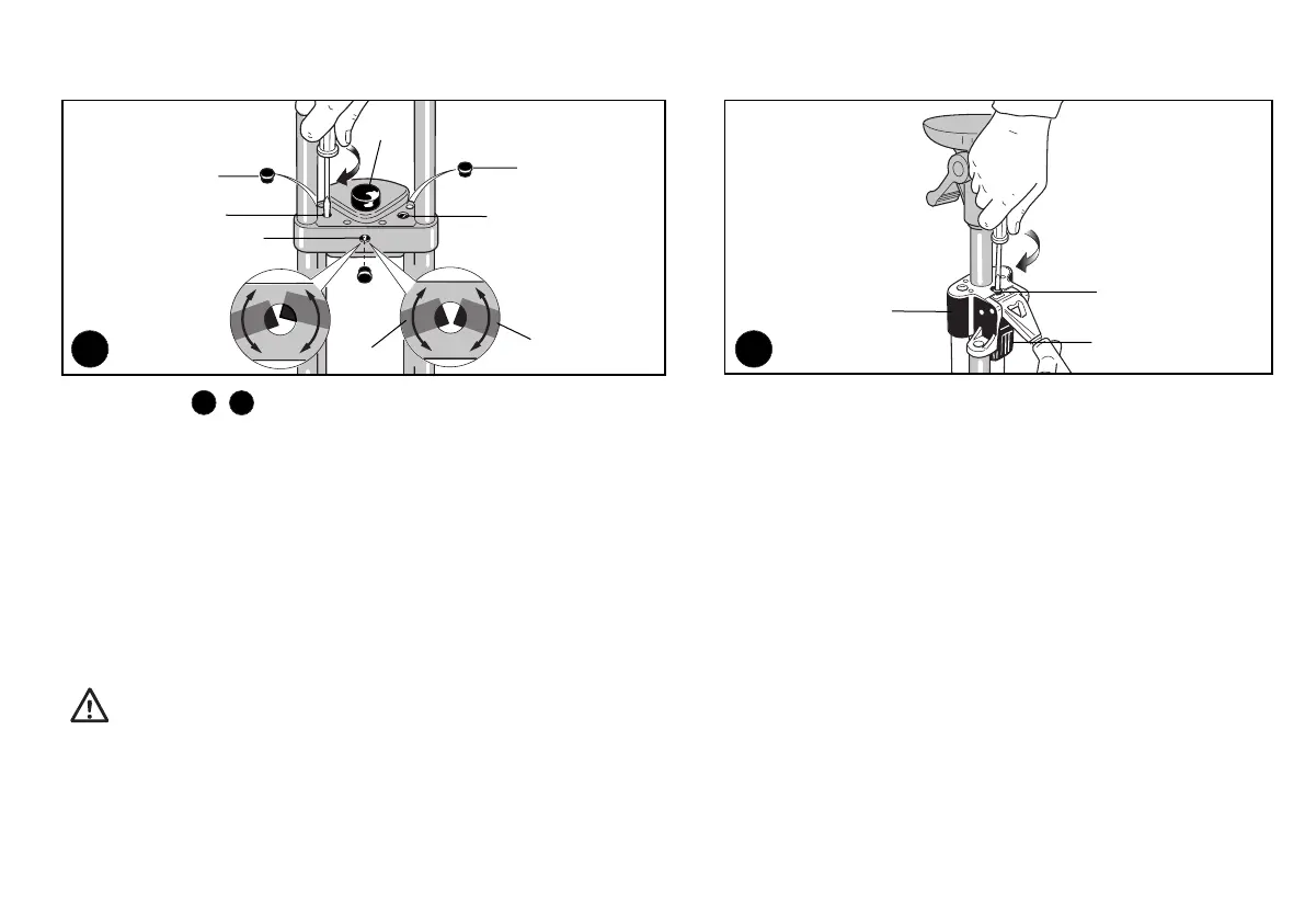
MAINTENANCE
If slipping occurs, clean the leg-tubes with a tissue. In case the cleaning is not sufficient, the tripod is user-serviceable and can be adjusted:
UPPER COLLAR
1. Remove the protection caps “S”.
2. Turn the two adjustment screws clockwise “T” not more than 15-30° of a turn and try the leg’s tightness by pushing down on the tripod.
3. Do not overadjust, otherwise the legs will not completely slide out even while pushing the button "E".
4. Check alignment by looking through the inspection hole “V” and pushing in the unlocking button "E". Proper adjustment occurs when levers "Z" align as in fig 18.
Please note: tightening the screw lowers the corresponding lever, loosening raises the corresponding lever.
5. Replace protection caps “S” and "V".
LOWER COLLAR
1. Turn the tripod over to reach the lower collar “X” adjustment screw (see fig. 19).
2. Turn the adjustment screw clockwise ”W” (fig. 19) not more than 15-30° of a turn and try the leg’s tightness by pushing down on the tripod.
3. Do not overadjust, otherwise the legs will not completely slide out even while pushing the button "F" (fig. 19).
• Adjust screws in very small increments. Only slight adjustments are necessary.
• Check the tightness of the leg after each small adjustment and stop when locking is achieved.
• Do not loosen the screws more than one turn, the nuts could become unscrewed.
18
19
18 19
 Loading...